Mercedes-Benz Forum banner

Seat memory retrofit

13K views 41 replies 2 participants last post by  KevinH2000  
#1 ·
I have previously installed a set of C63 AMG seats in my C230. You can read about my project here: BenzWorld thread. There are additional comments on MB World: C63 seat installation in a W203 Although the C63 seats support the memory function, I was not able install that feature. Another forum member (Saabotour) was able to take my work to the next level and add memory to his C63 seat retrofit. You can check out his work starting at post number 34 of the MB World thread. The key difference between Saabotour's car and mine is that his started life with the memory function and mine did not.

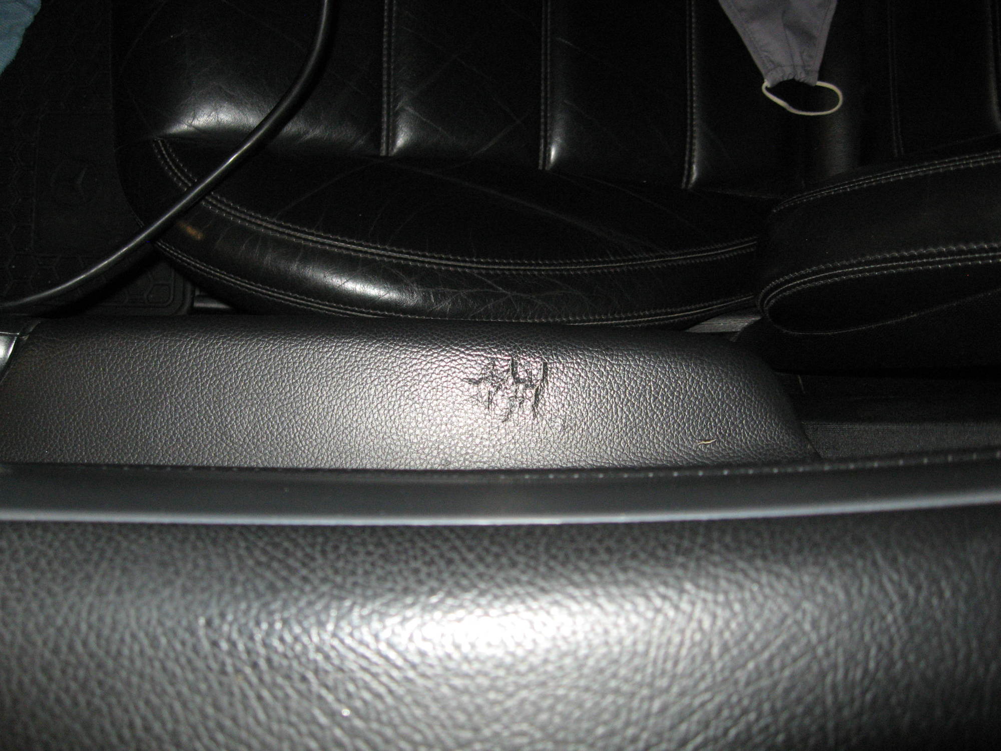
Because the driver's armrest on my car is starting to deteriorate, I started searching for a replacement.
Image

Deteriorated armrest

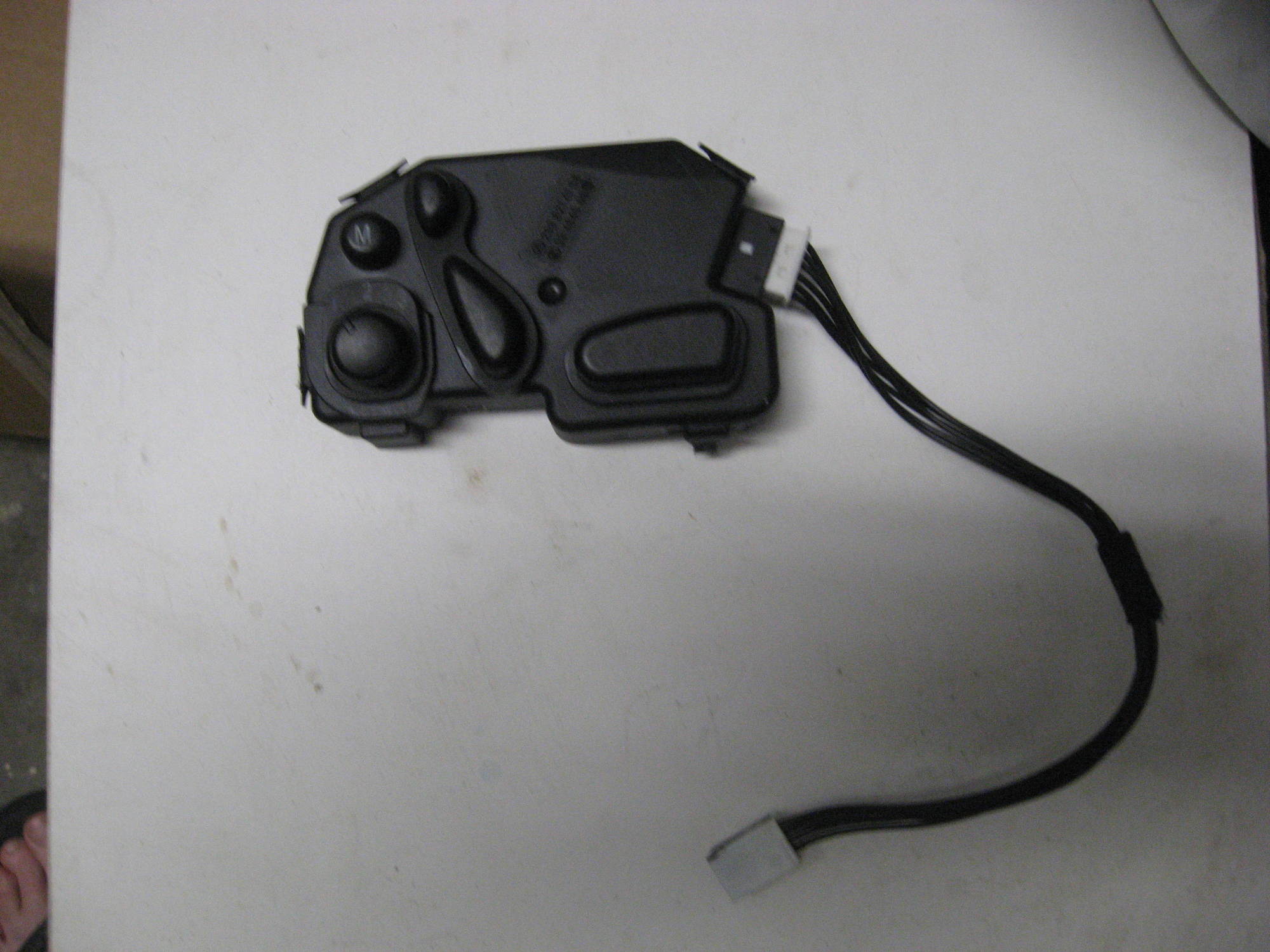
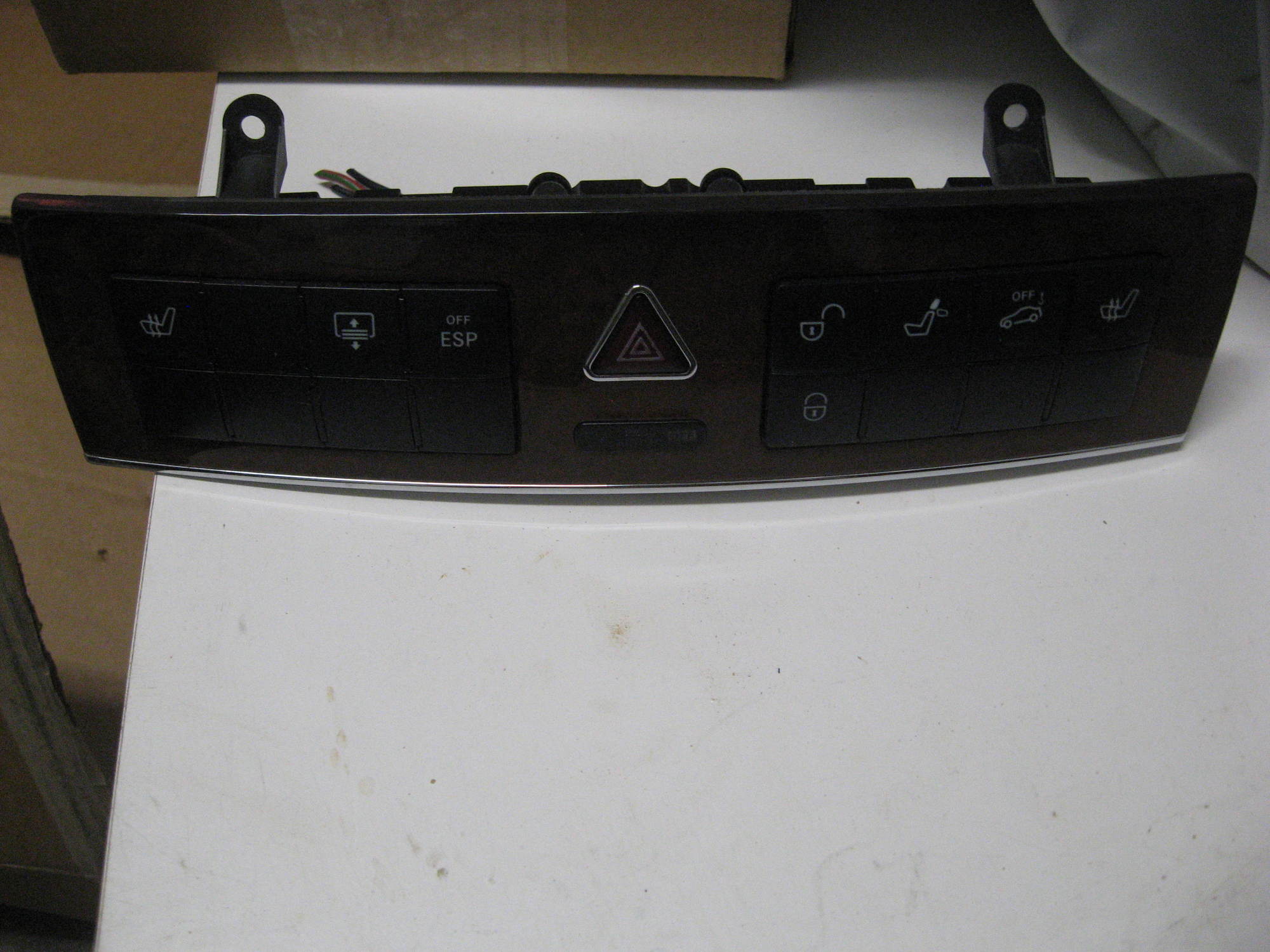
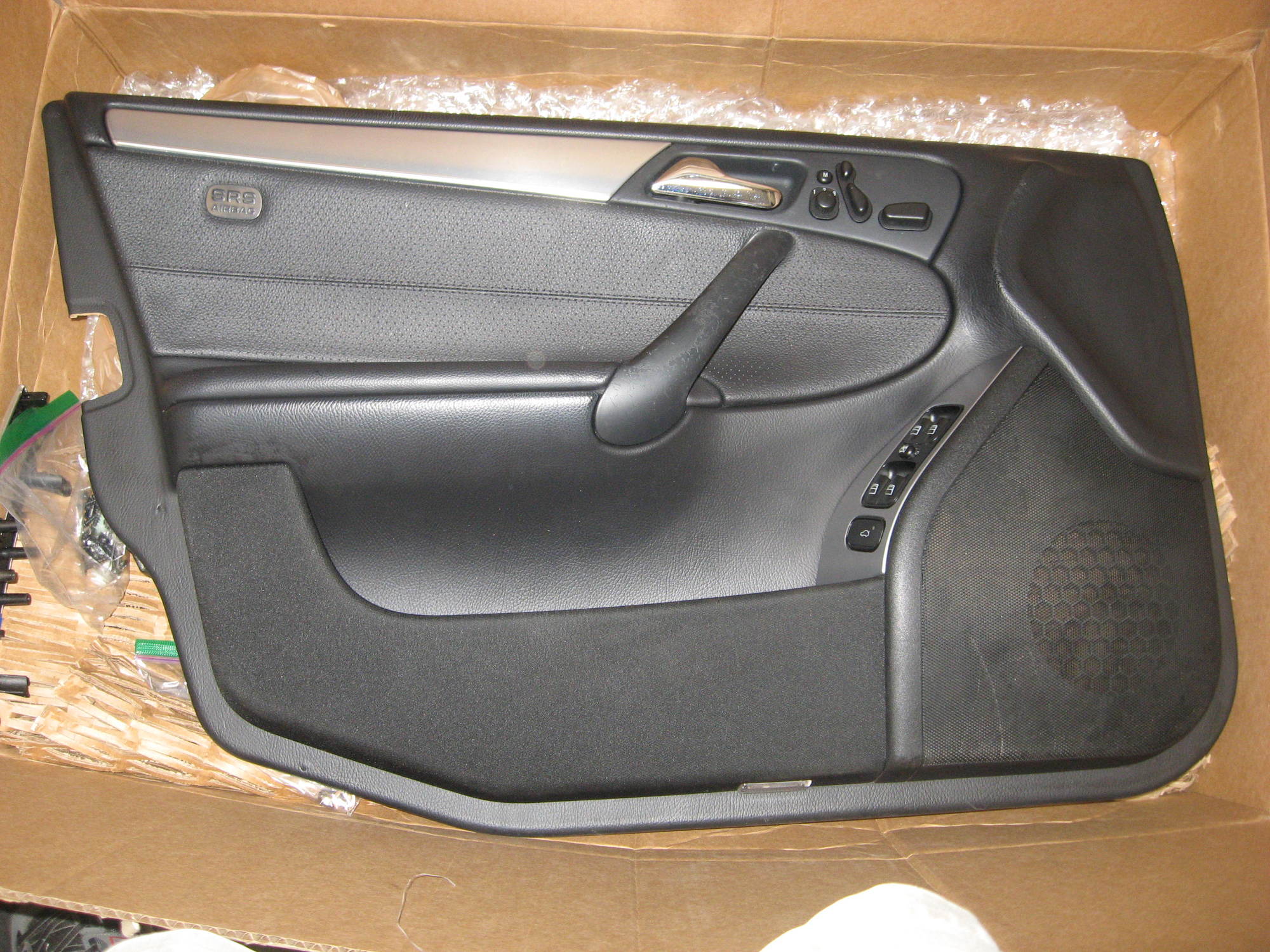
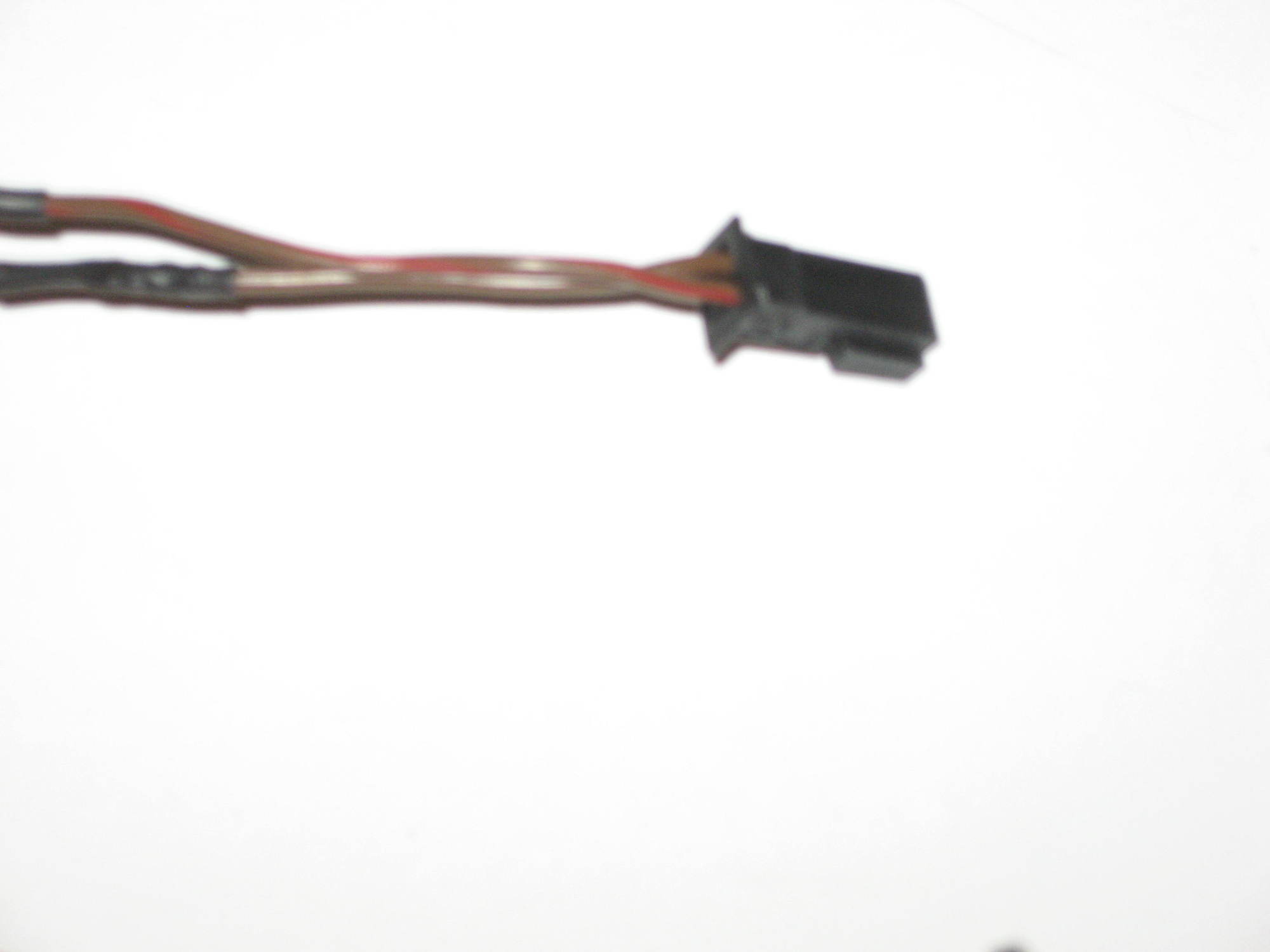
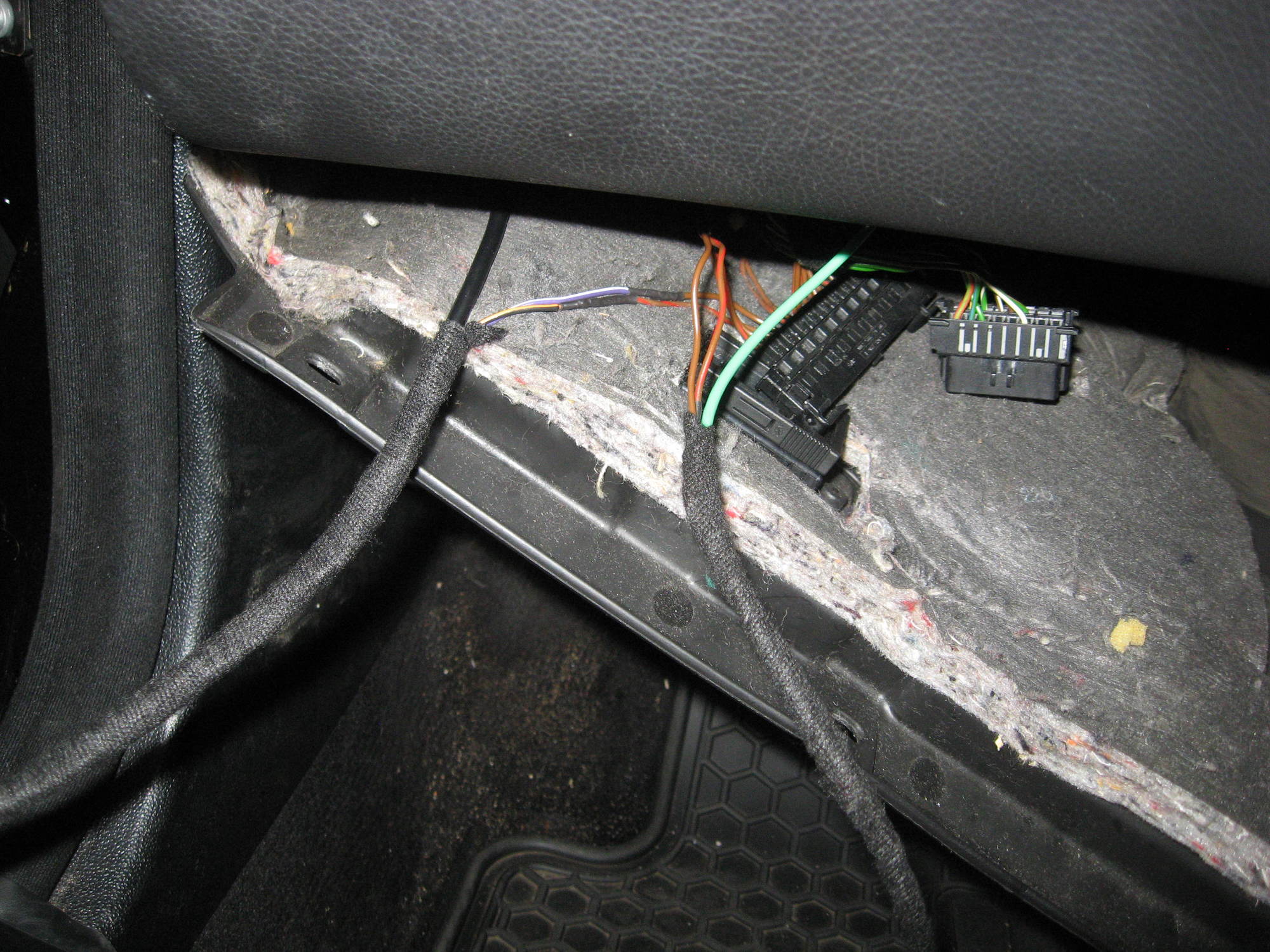
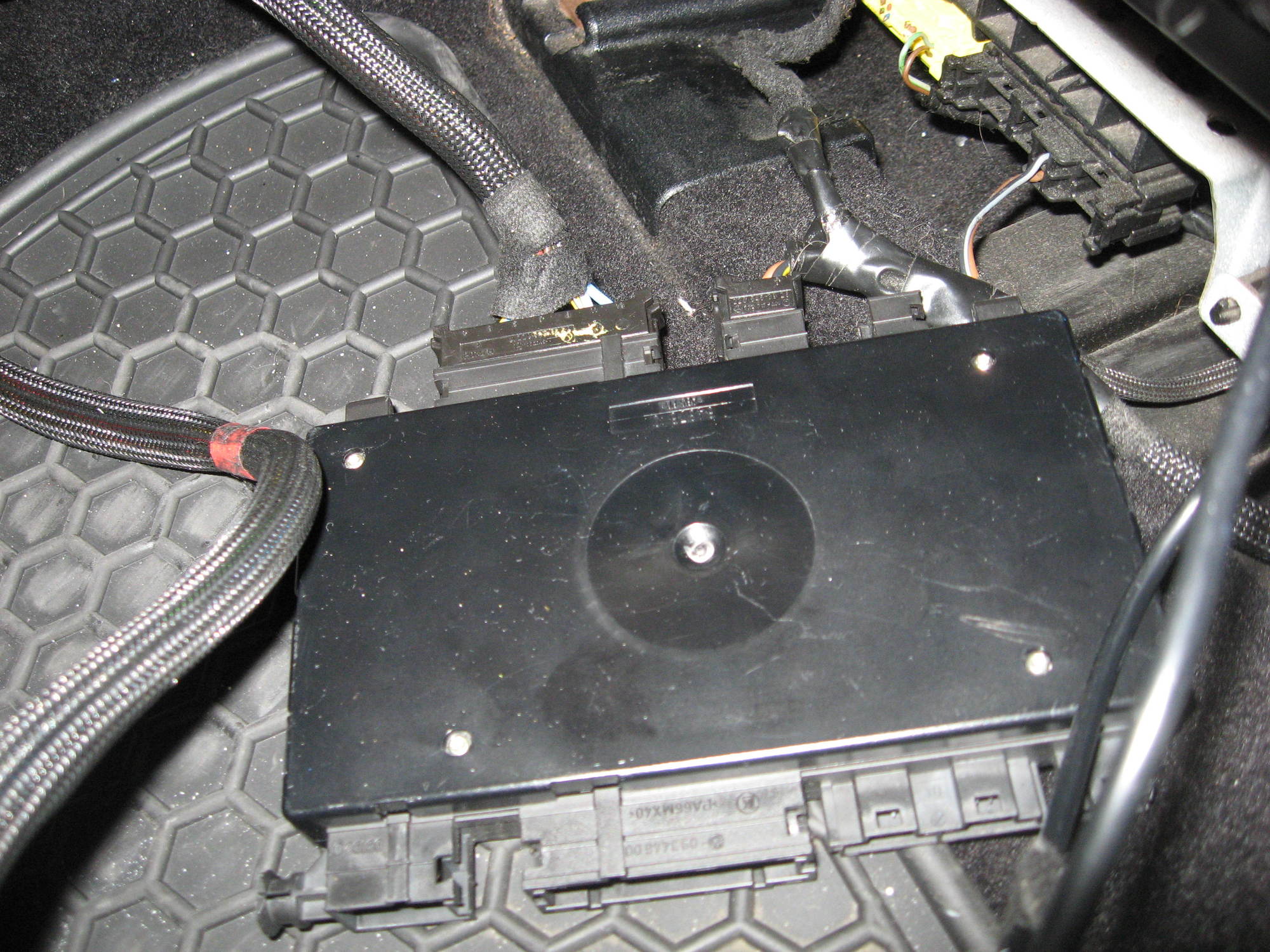
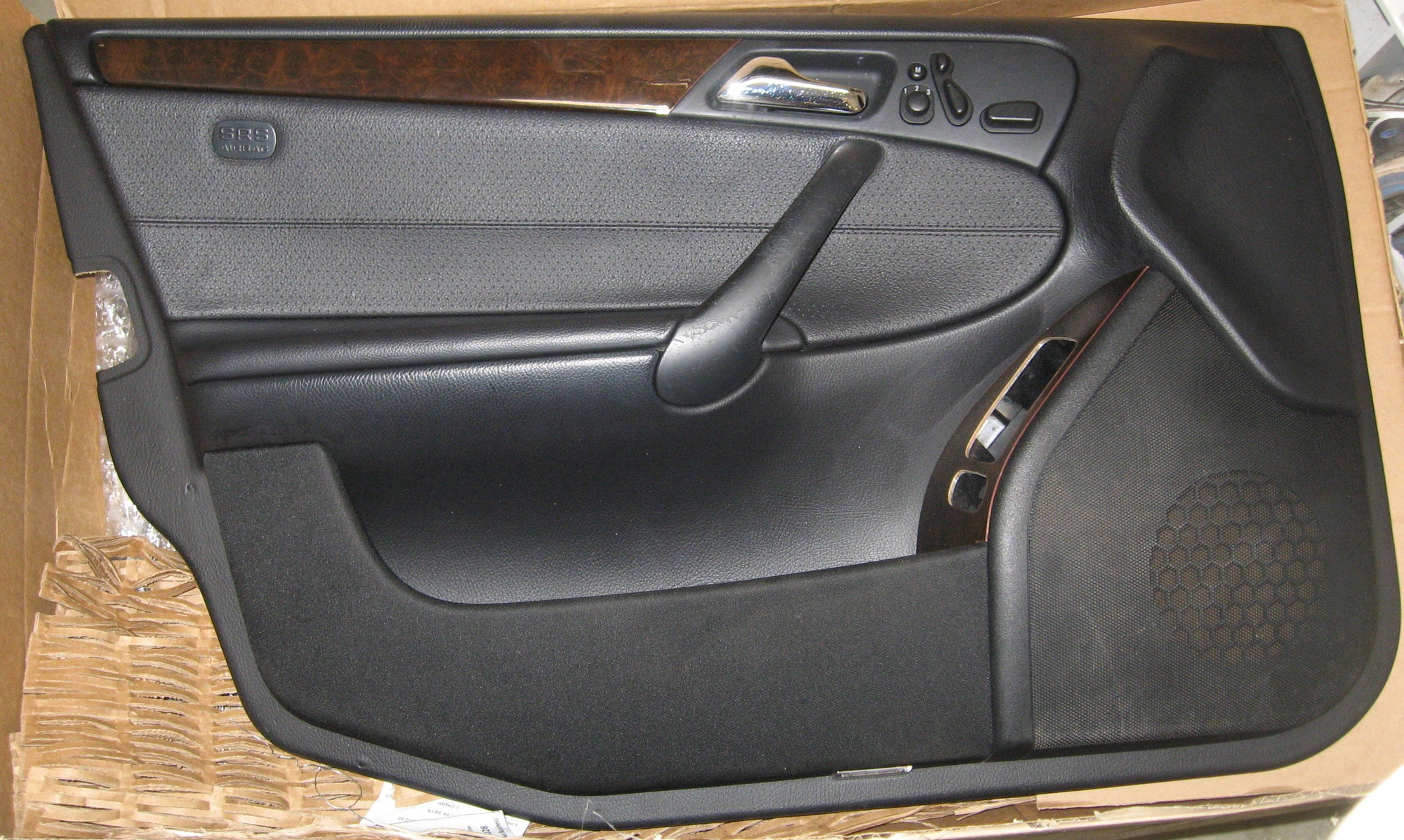
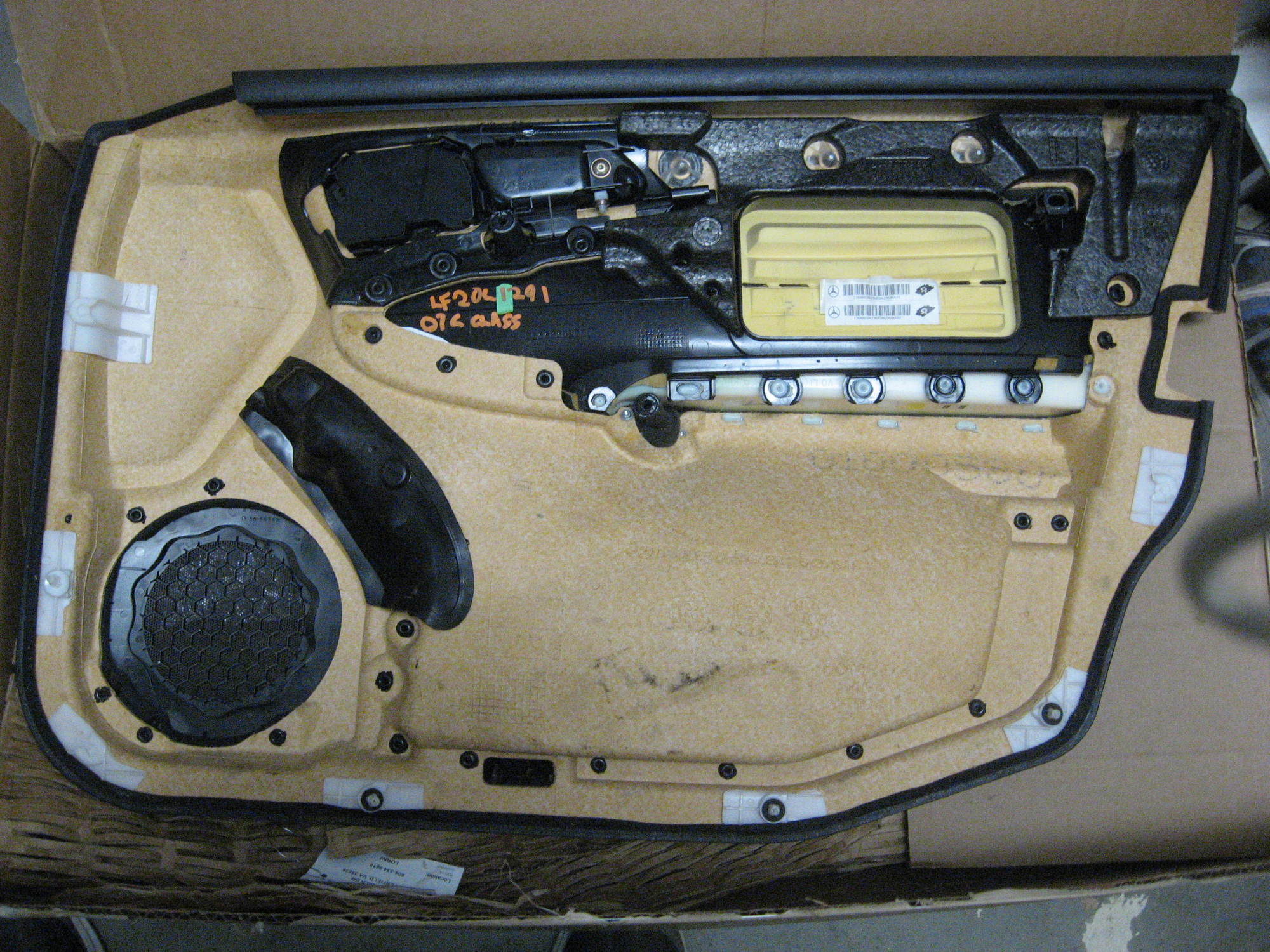
I found one in good shape that included the seat memory controls and bought it.
Image

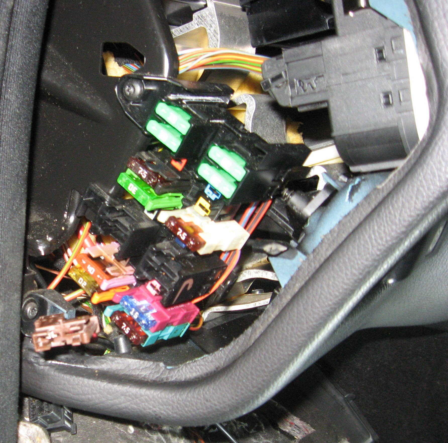
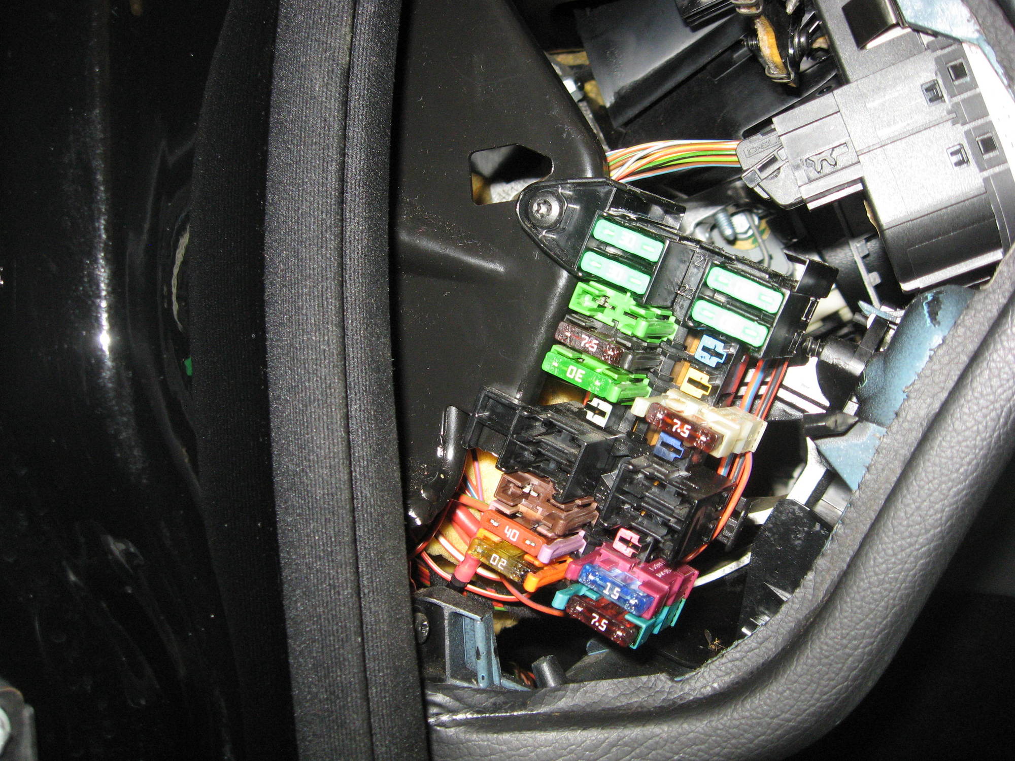
Door panel with memory seat controls

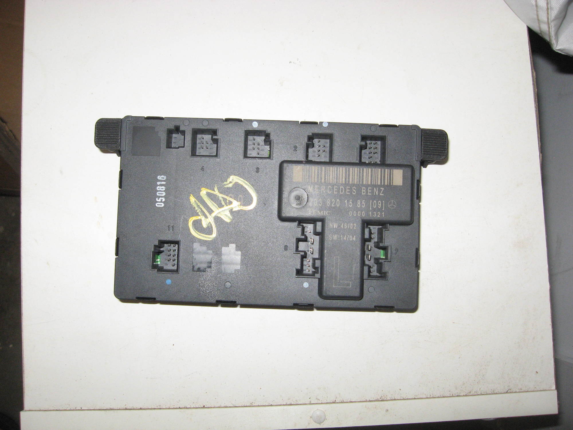
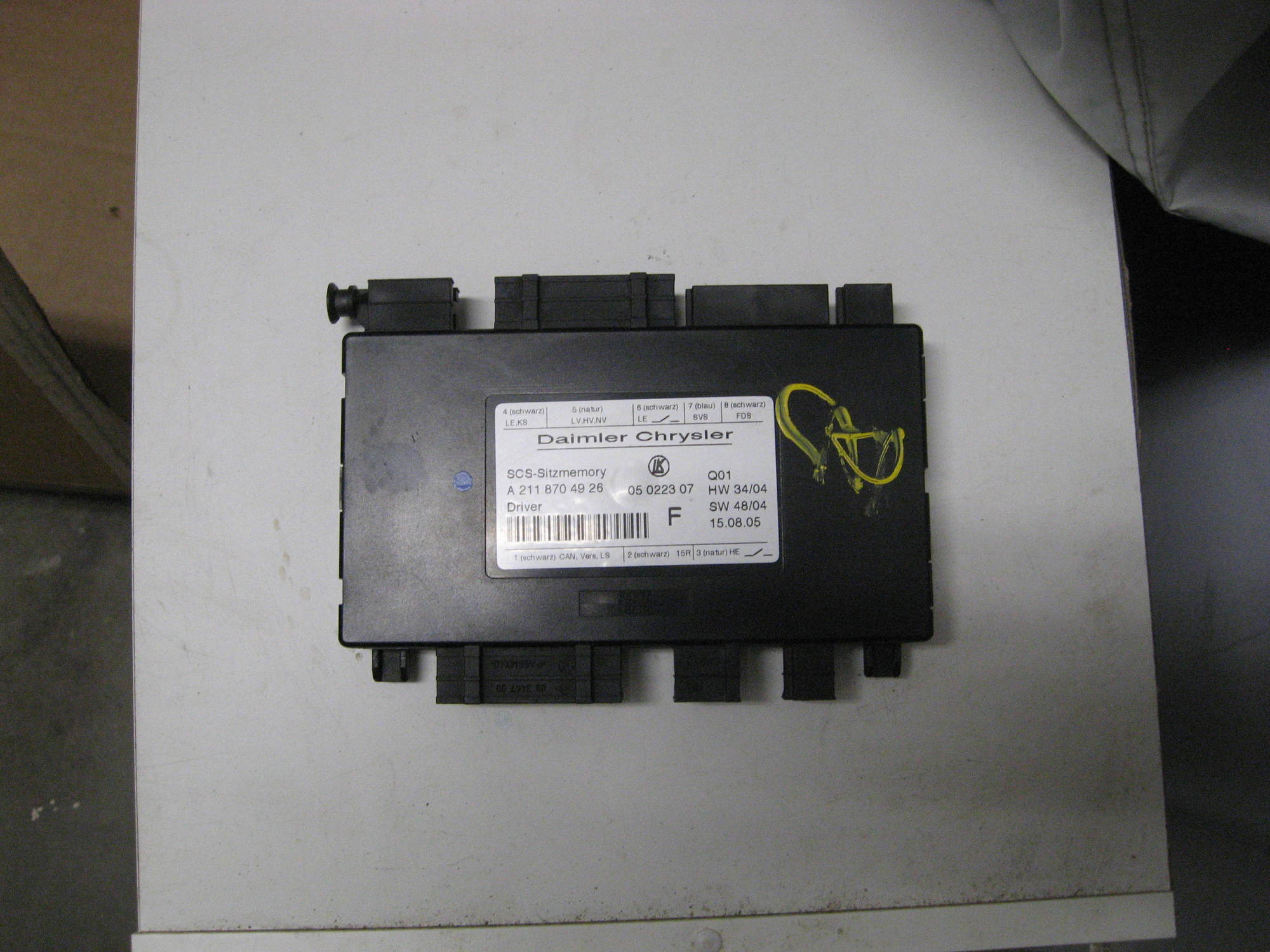
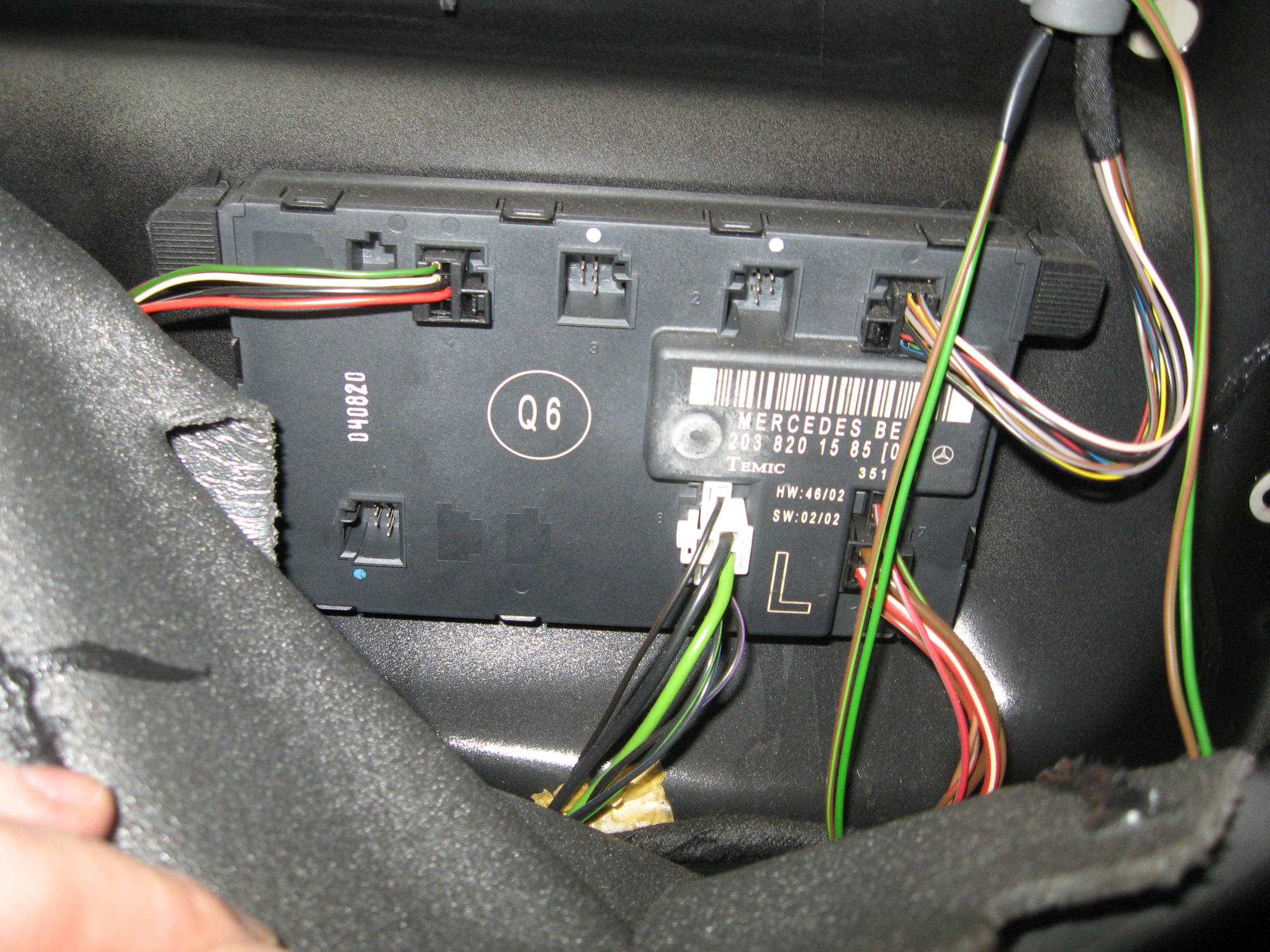
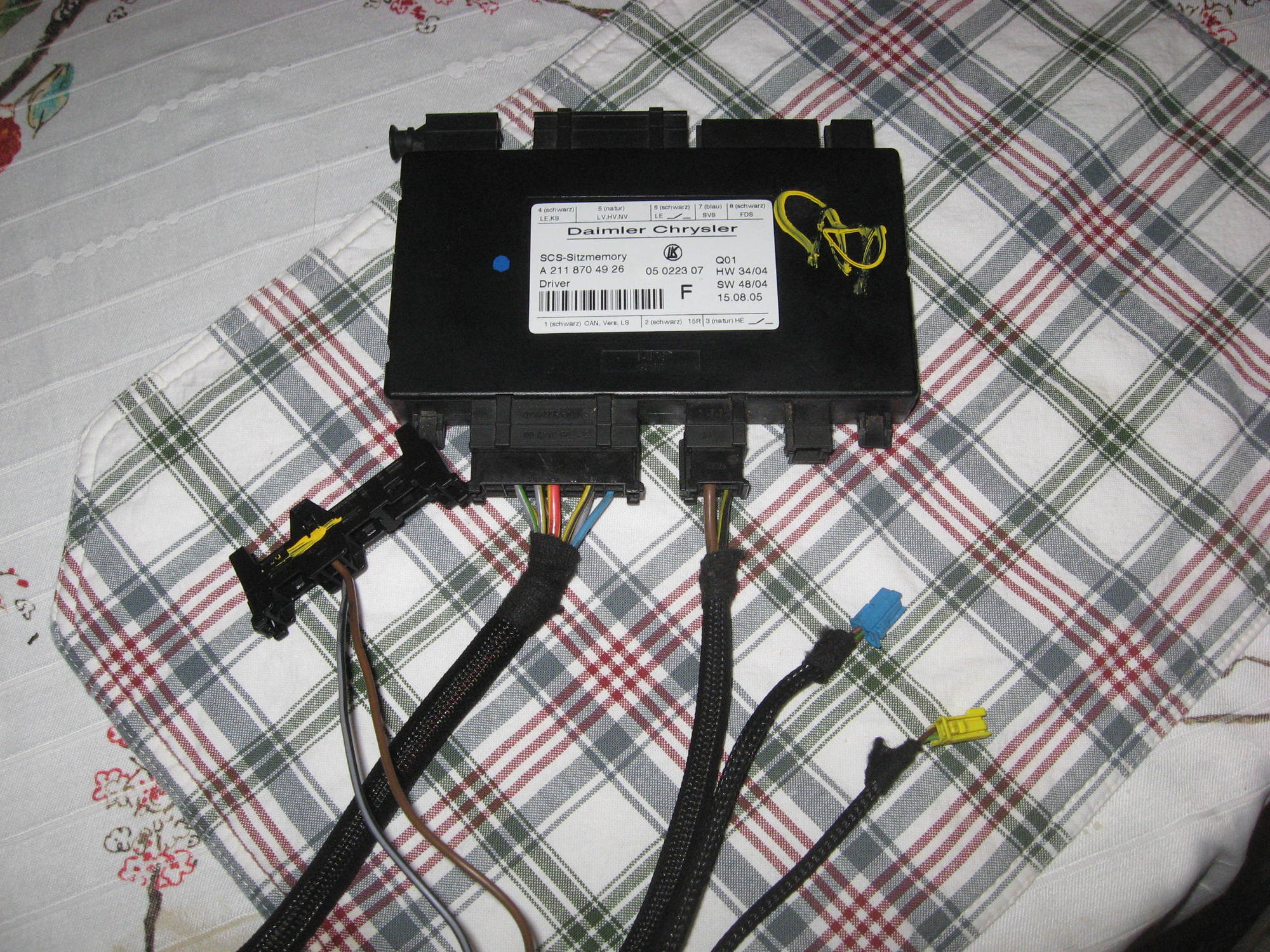
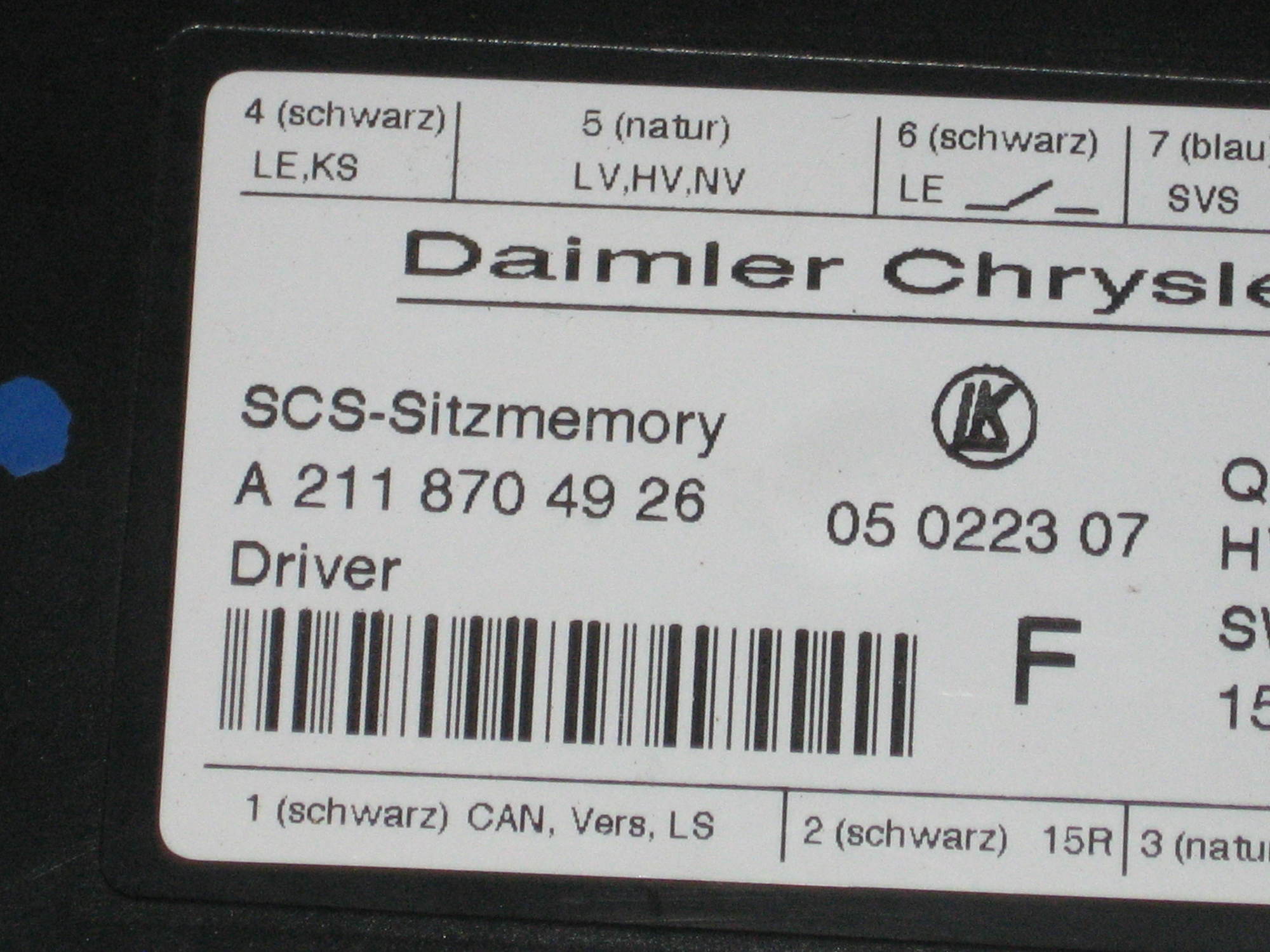
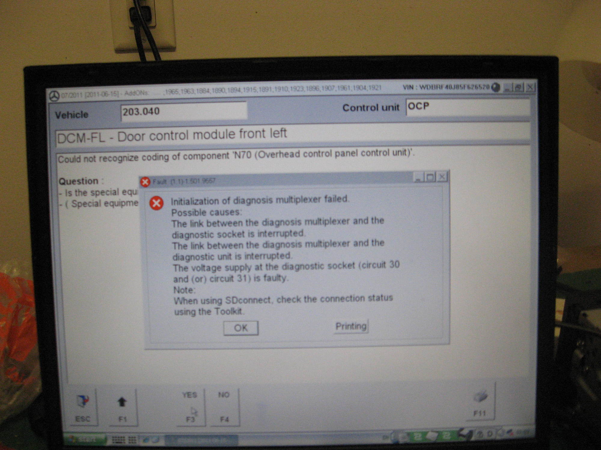
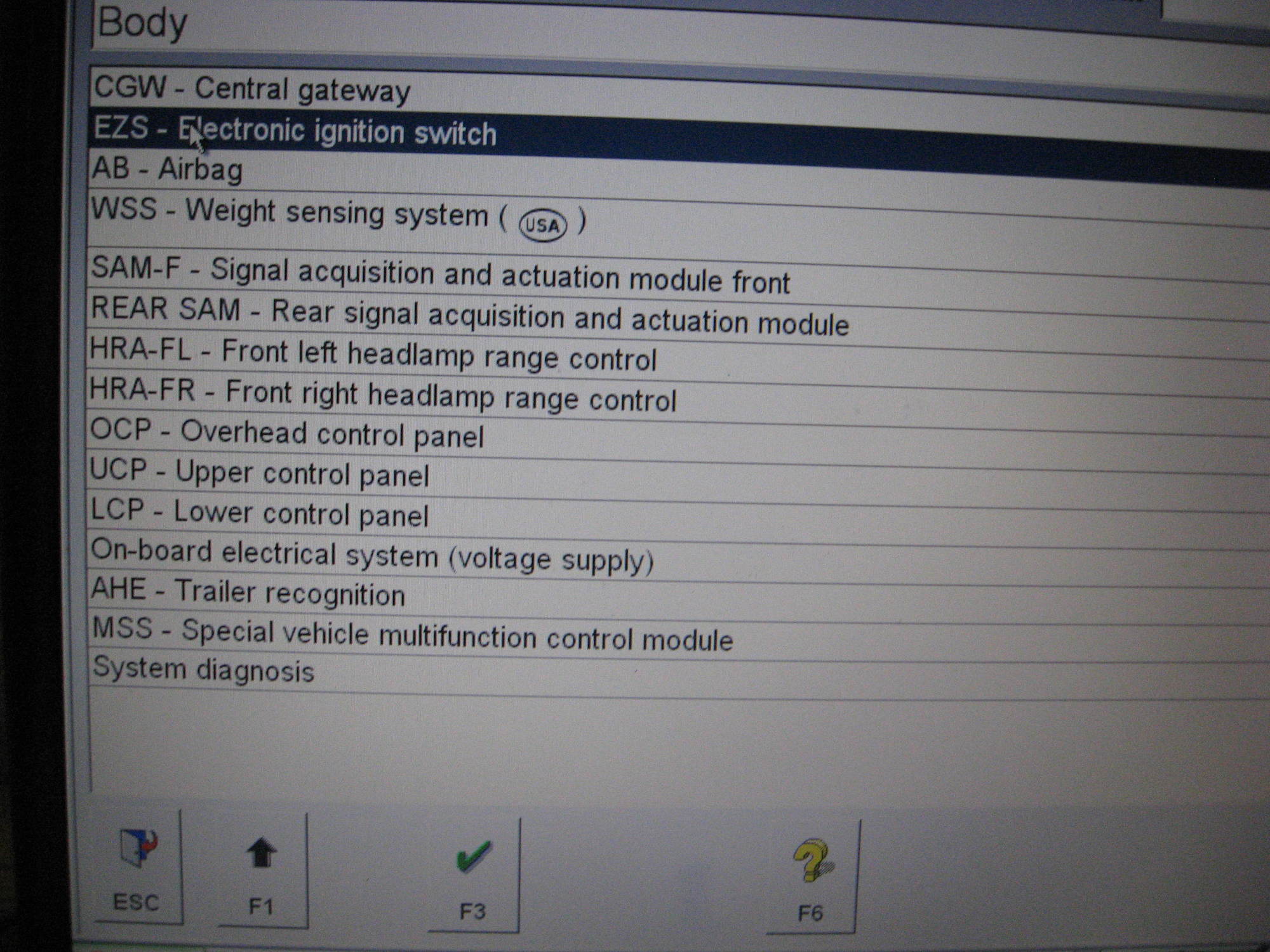
I've garnered some information from Saabotour's work. Specifically, the seat control module in the C63 seats is not compatible with the W203 door controls. Although I have the seat control modules for the C63 seats, I will need to exchange them for the W203 module which is part number A 211 820 85 85. This seems to have been used on several MB models. If someone has one to sell at a good price, please feel free to send me a message with the details.

I also believe that I won't be able to achieve all of the functionality that Saabotour achieved. It appears that the memory seat function was tied into the outside mirrors and the steering wheel and includes a convenience feature that moves the seat and steering wheel when the driver turns off the car. However, I will have several benefits if I am successful - 1. The seat controls on the seat bottom are difficult to reach because the C63 seats are wider than the stock C230 seats. I will have better access to the controls mounted on the door. 2. The current controls only work when the car is on and that can be inconvenient especially when my wife drives the car and leaves the seat too close to the steering wheel for me to enter the car. 3. It will make the car seem more complete.

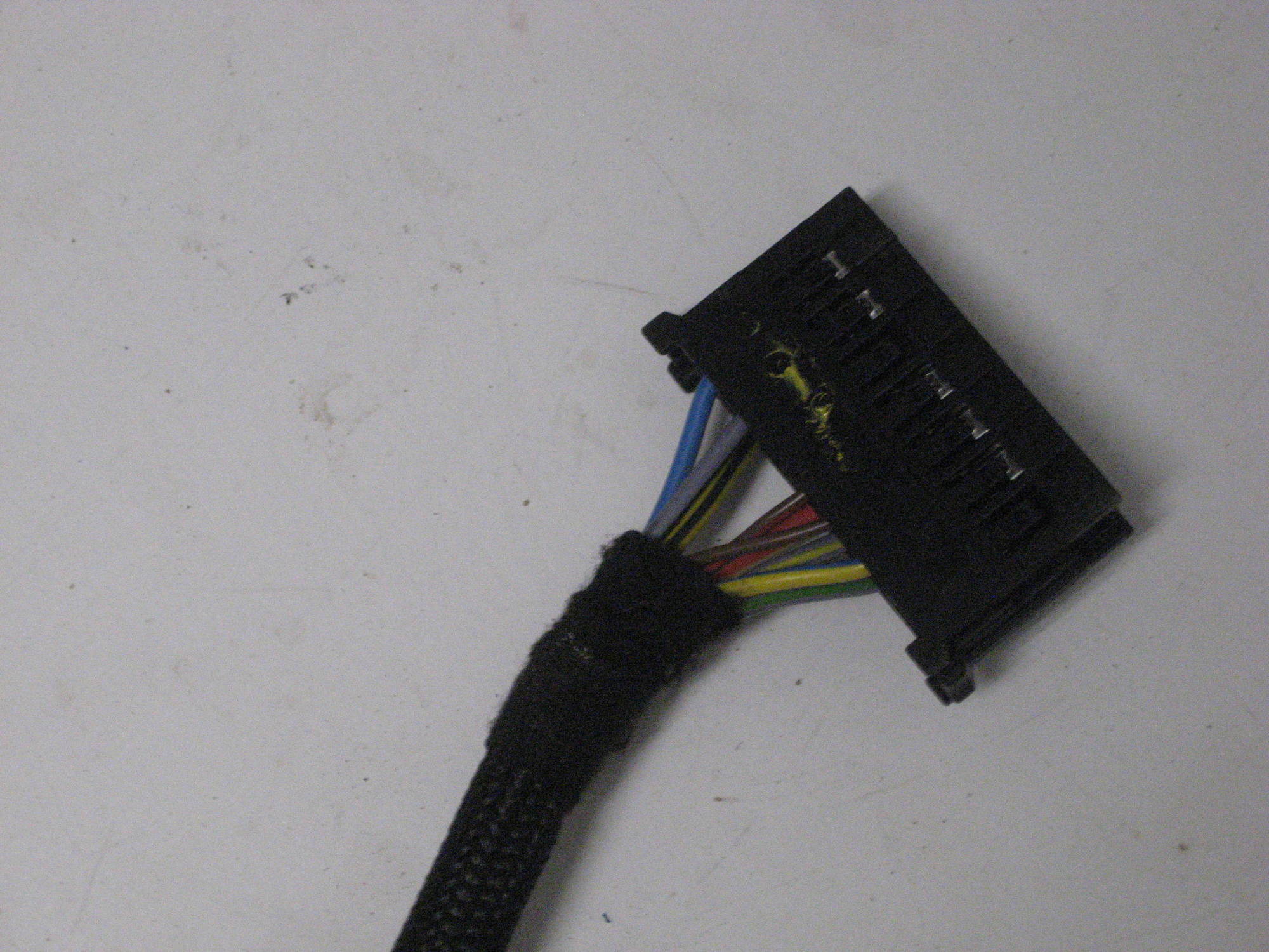
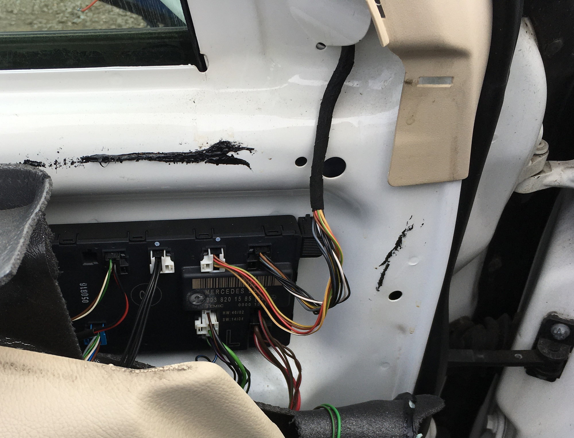
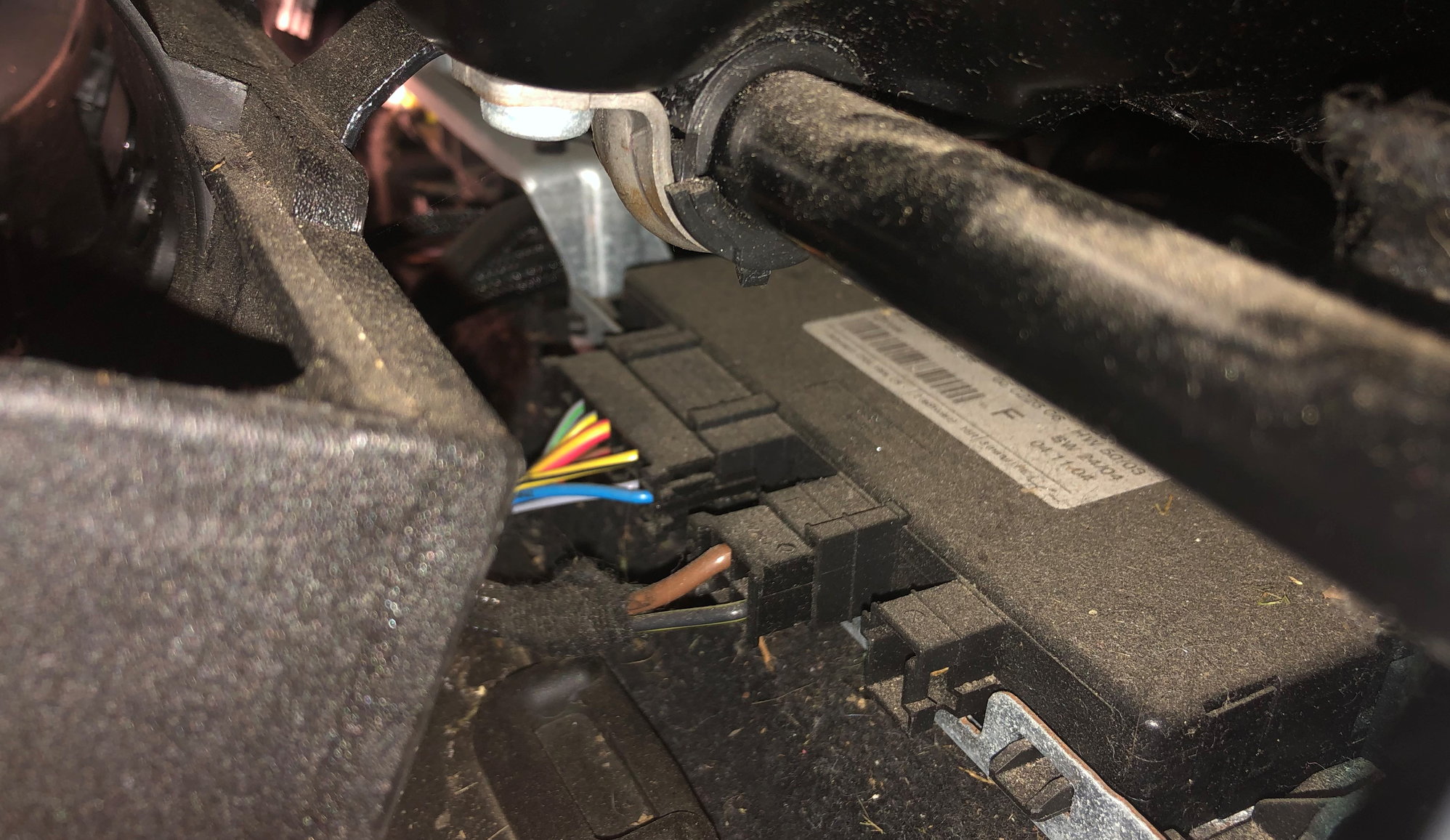
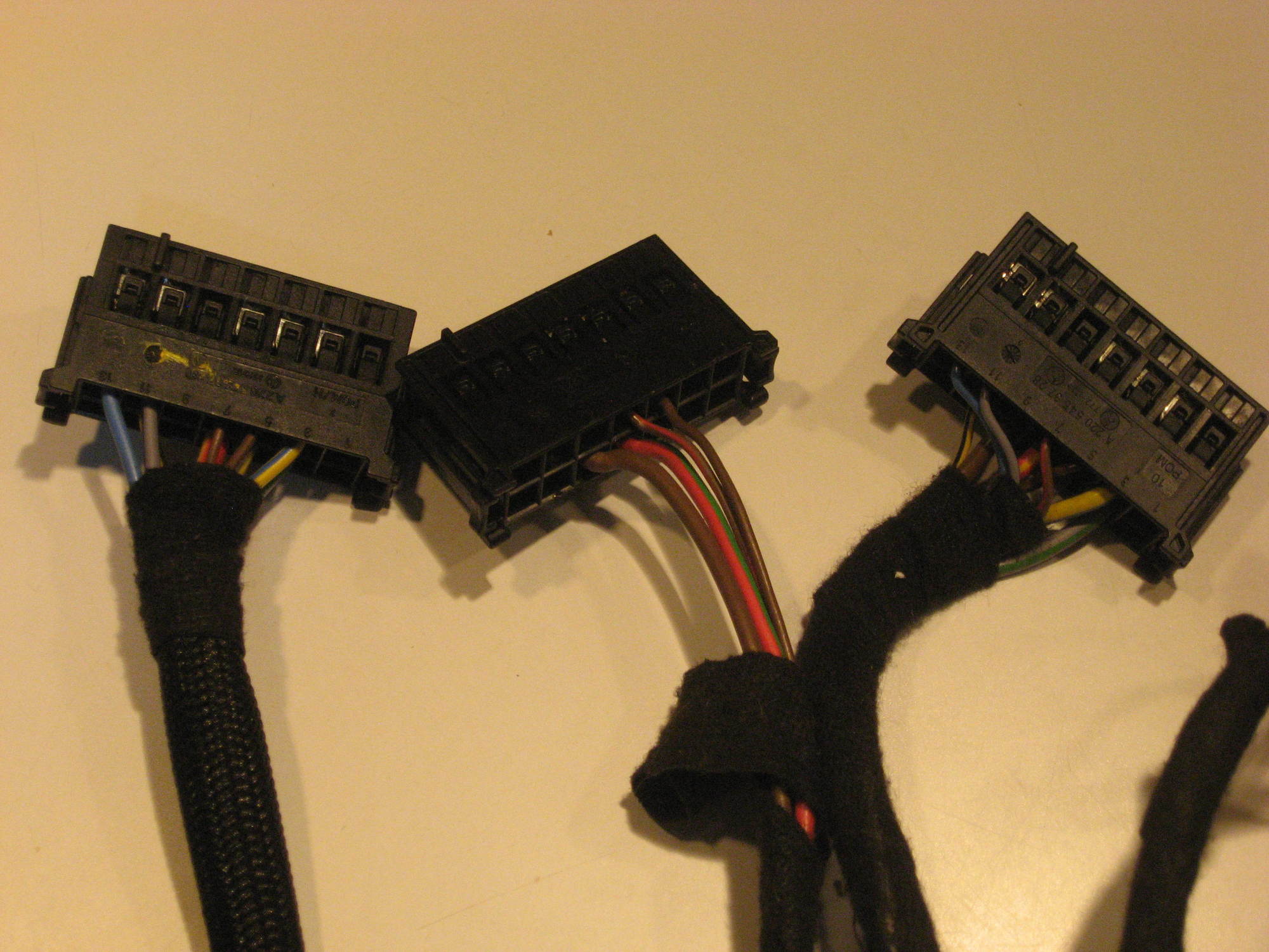
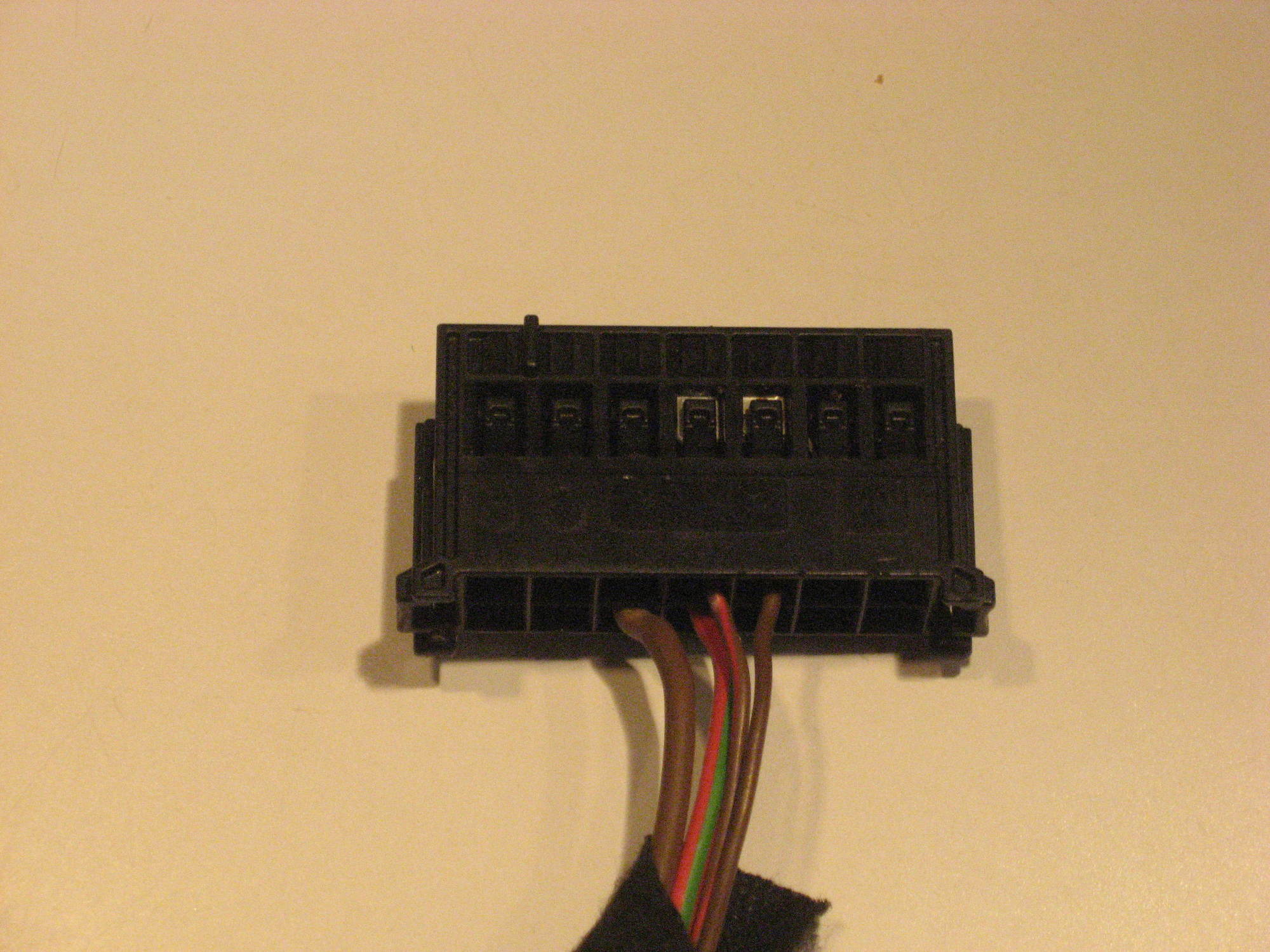
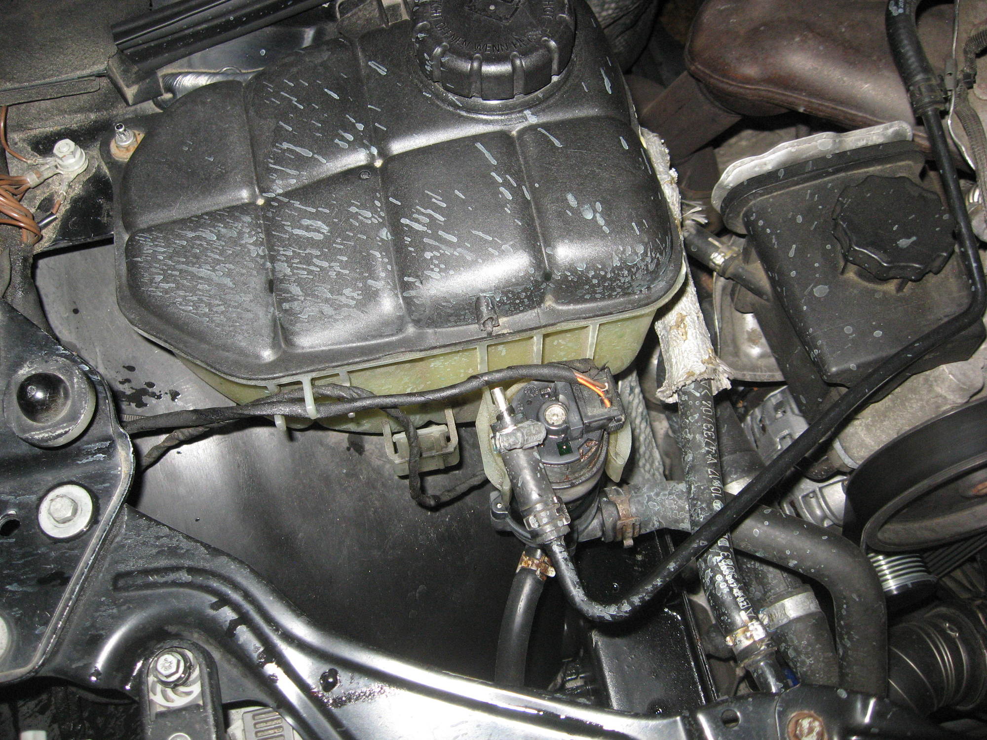
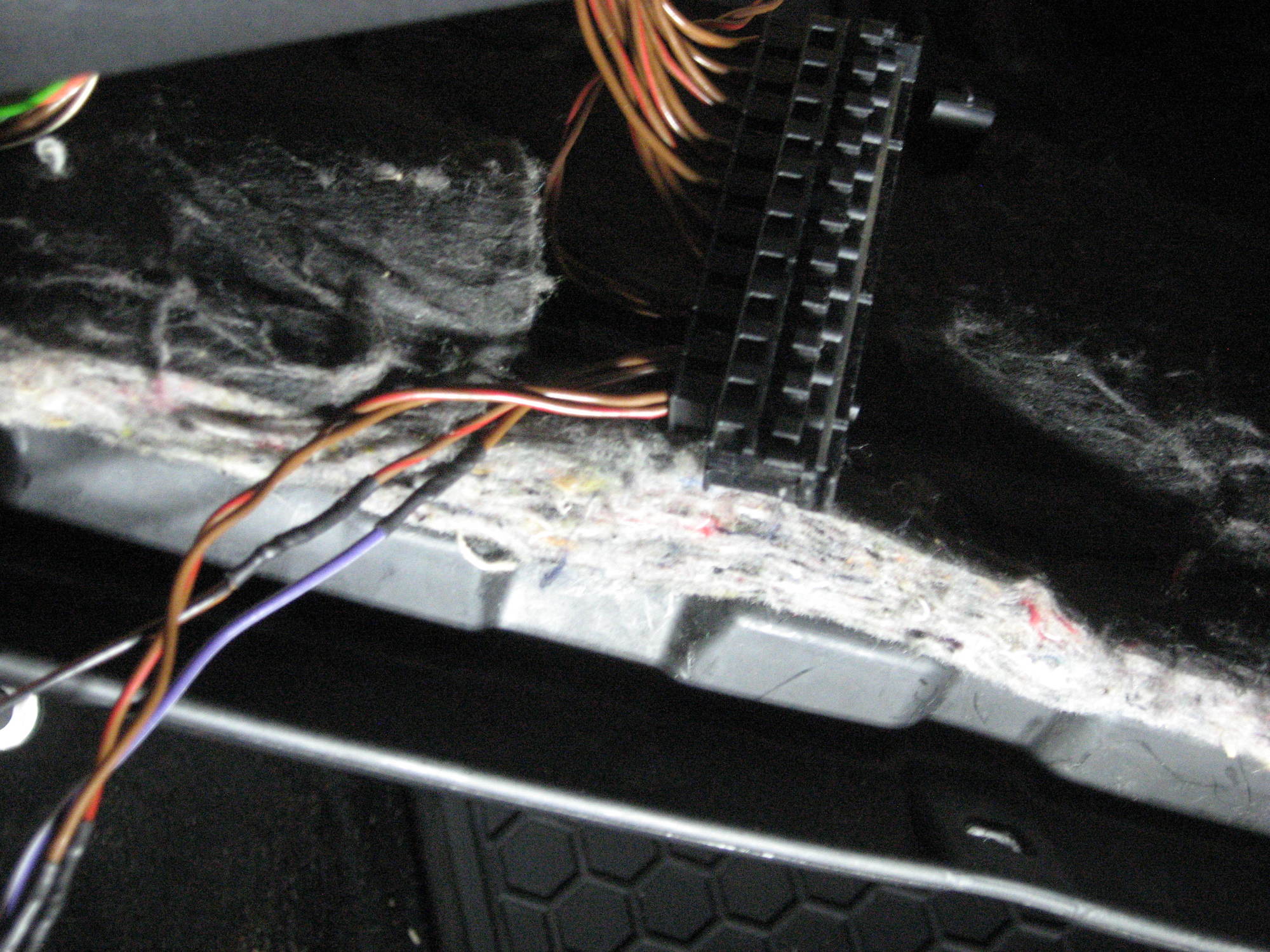
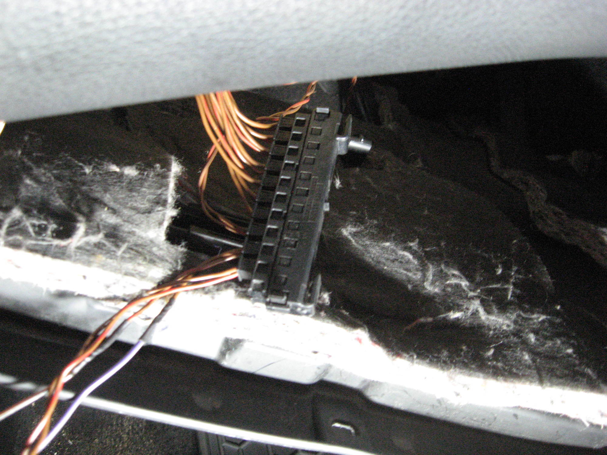
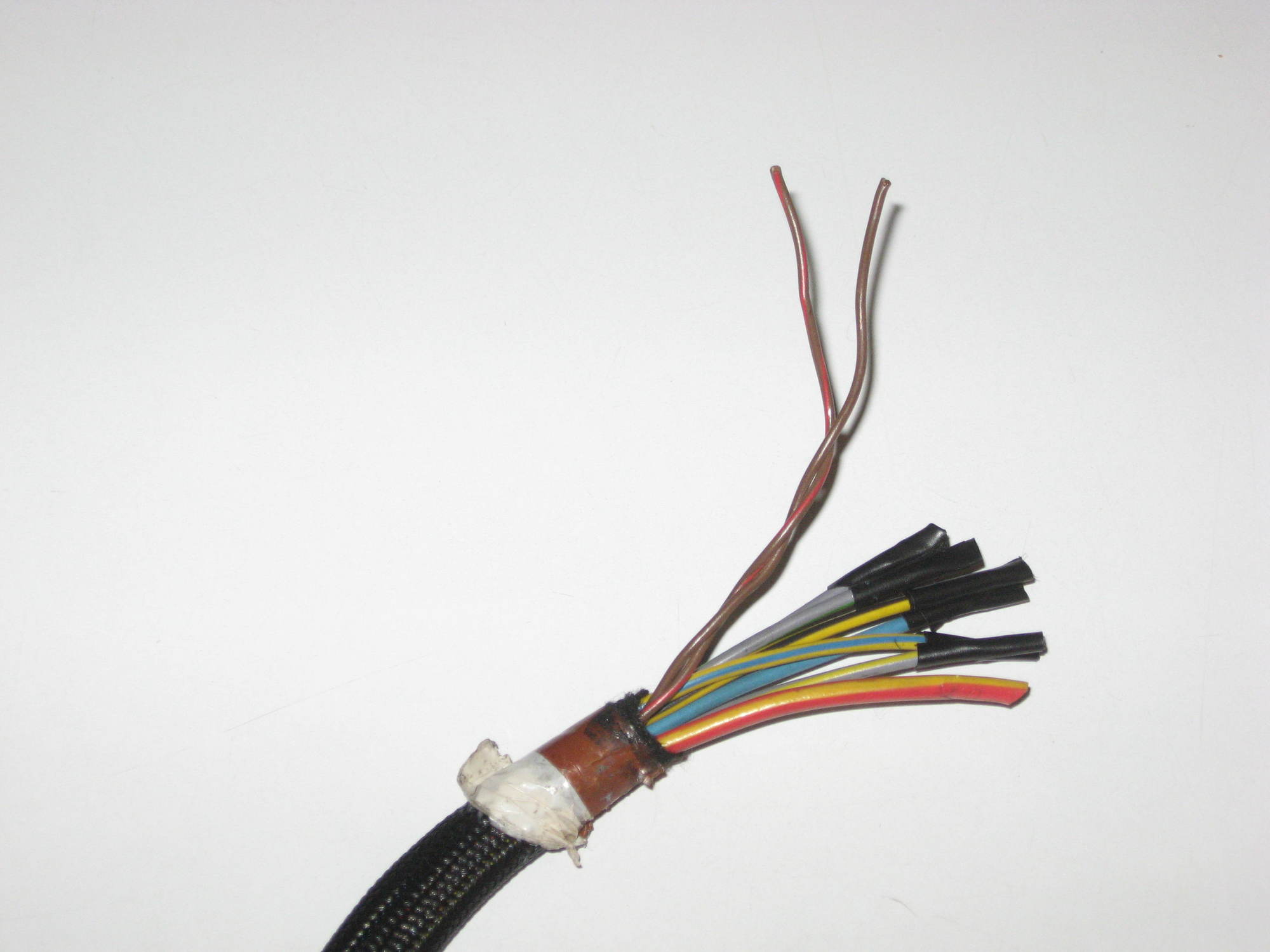
The biggest challenge I see is with the wiring. There was no wiring inside the door panel and I will need to see what is inside my door. I doubt that there is a harness that plugs into the seat control, but I may be pleasantly surprised. If there is no wiring, it appears that I will have two options: 1. Attempt to integrate the seat controls and the seat control modules into the CANBUS or 2. Wire the controls directly to the seat modules.

Image

No wiring inside the door

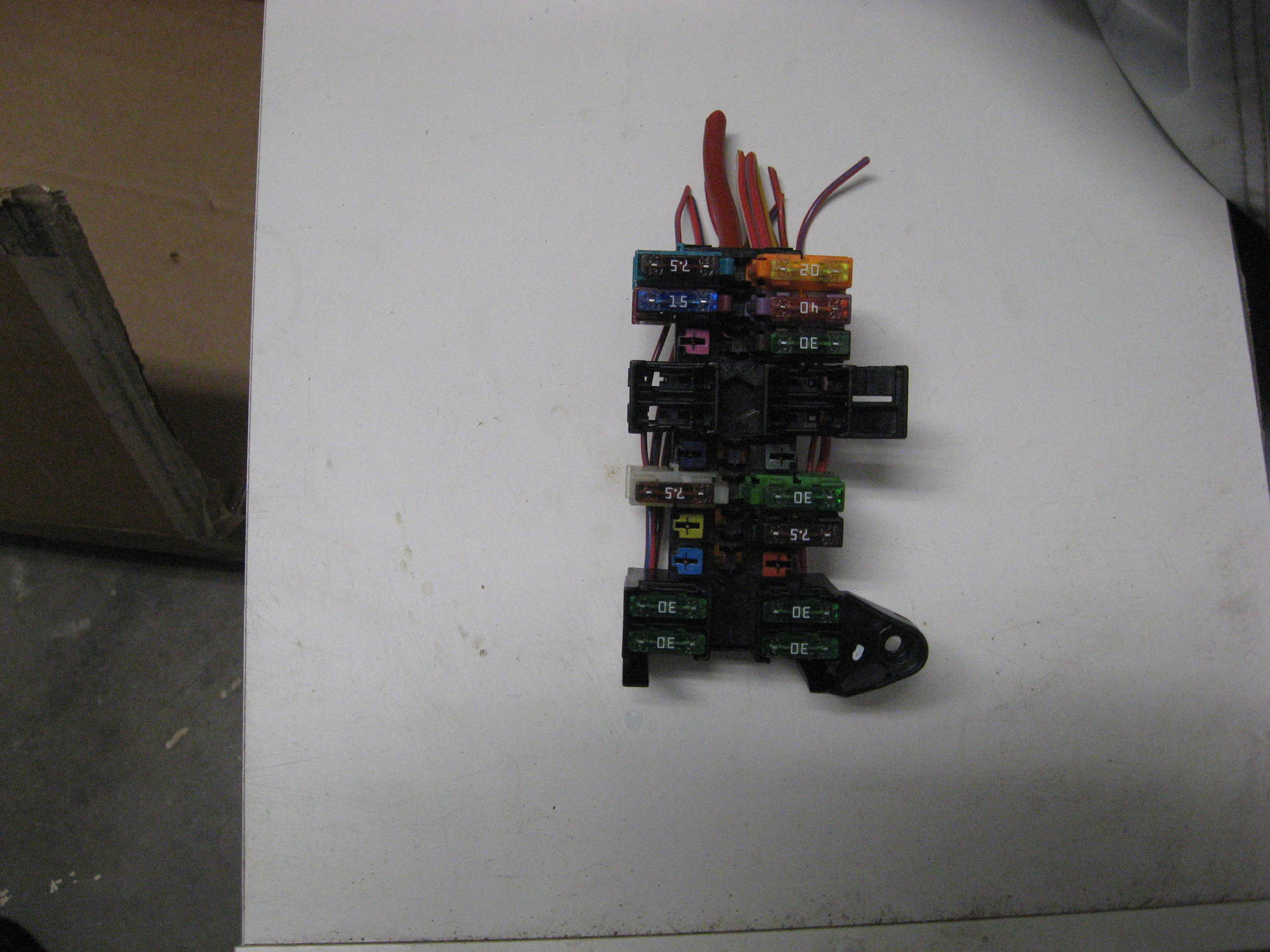
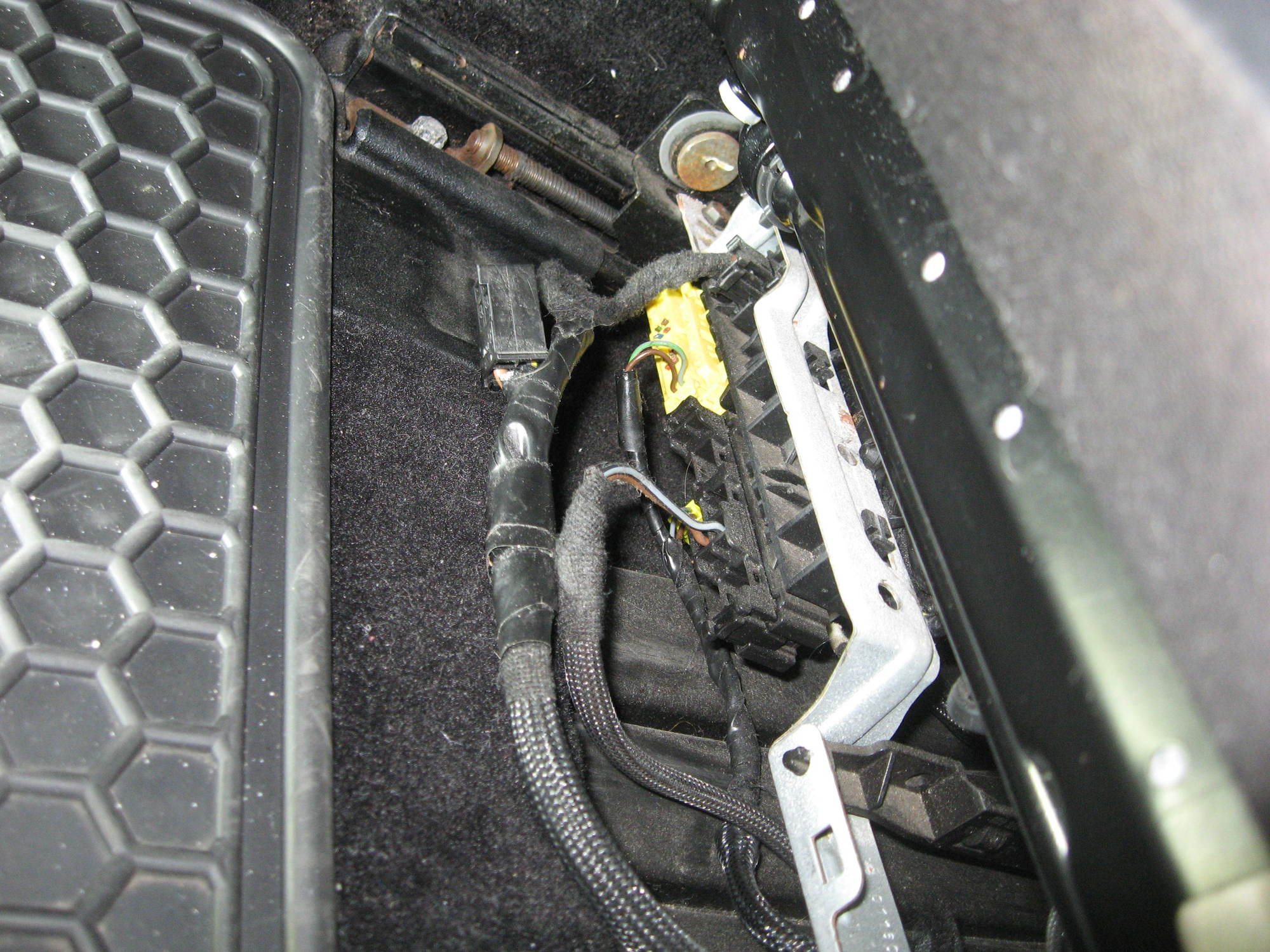
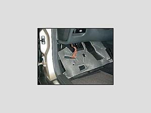
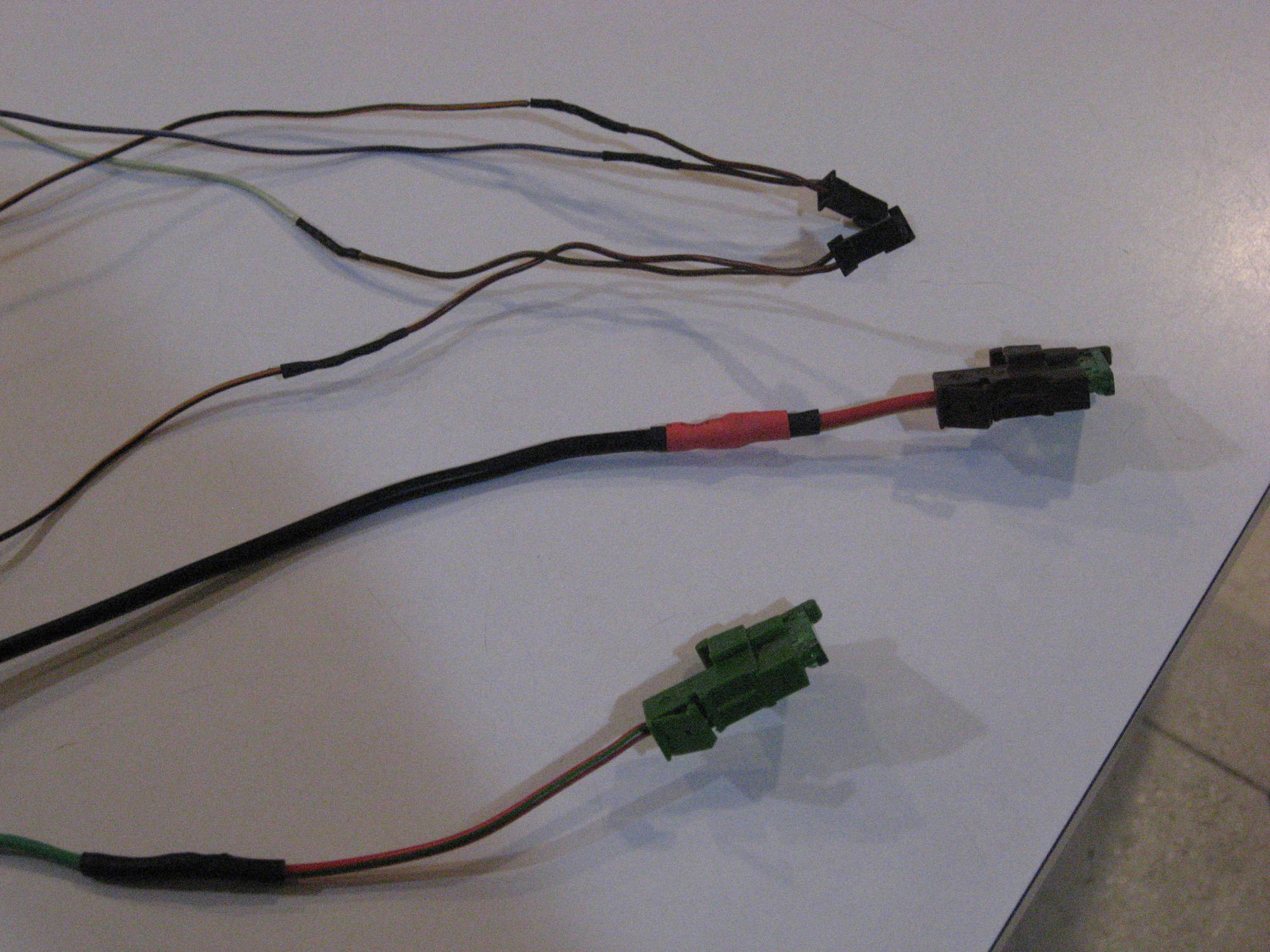
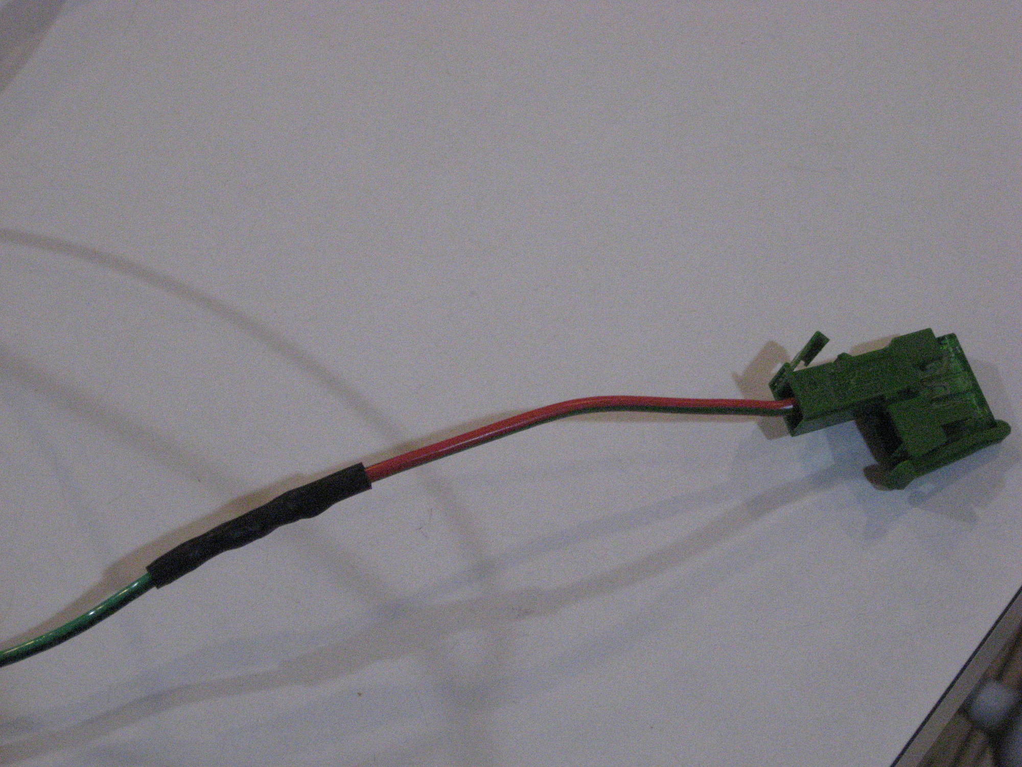
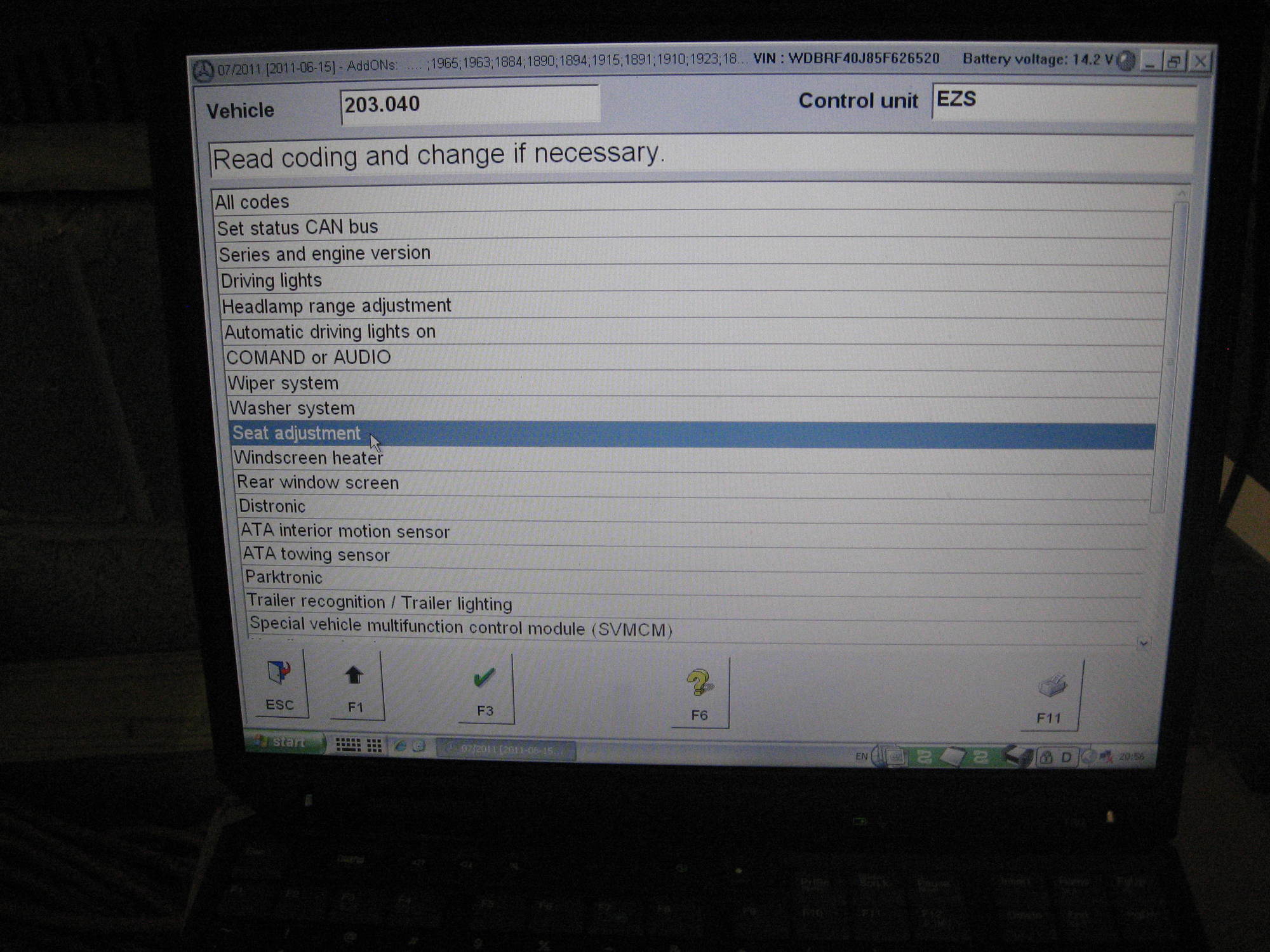
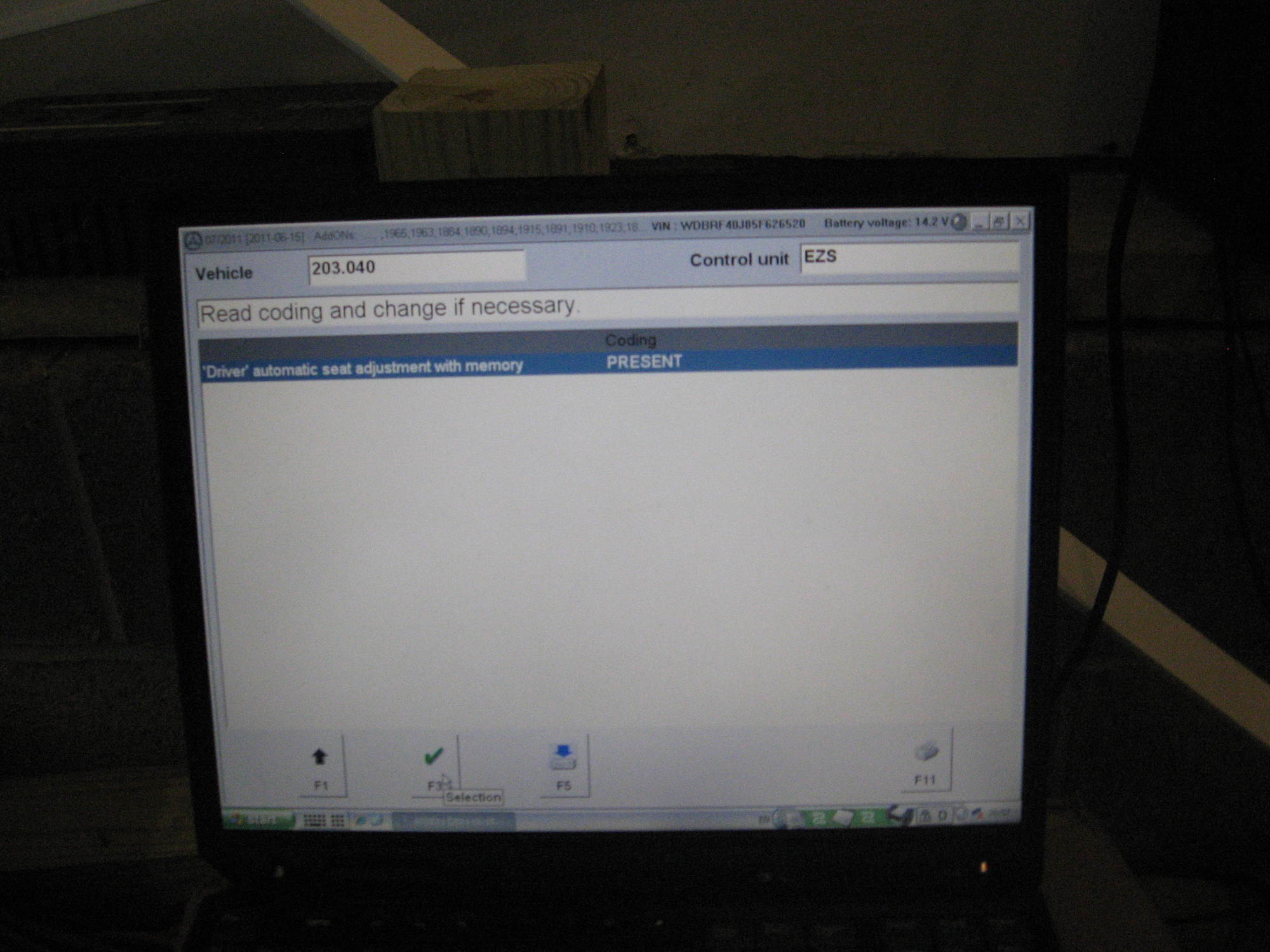
I've searched and have not found any posts showing that anyone has succeeded with a memory seat retrofit in a car that didn't have factory memory seats. But, if anyone has done this, please share your methods. I have been able to determine that the Rear SAM appears to be the control center for the seat memory function and that I may need to install some fuses in the Rear SAM if I integrate the control in the CANBUS. I also determined that there are six pins on the seat control module. My assumption that two of the pins are power and ground and there are two high CANBUS and two low CANBUS signal wires. One set of CANBUS signals would be produced by manipulating the controls to directly move the seat. The other set of signals would be produced by activating a memory setting.

The way I look at this, the worst that can happen is that I will have a cosmetically improved door panel with a non-functioning seat memory control. The upside will be improved functionality and improving my knowledge about how the car works.

I will provide updates as I move forward but I will appreciate any feedback or offers to sell parts needed for this project.
 
#4 ·
It's all CAN bus signals so the seat control plugs into the door controller. I'm not sure if that means you need a door controller specific to having memory seats, or if they all have that function with the socket.
 
#5 ·
I think I need to look inside a door with the memory seats and see how it is set up. The best-case scenario is that I will be able to plug the connector for the memory controls into a port that is readily accessible in the door.

I received a response to a post on the UK site I linked in my earlier post. The response was, "No wiring looms used that are not needed and so cue the quote of around ÂŁ2000,not sure if that includes VAT." That is not the response I hoped to see, but I'm not sure whether the response was based on direct experience with memory seat retrofits or general Mercedes frustration.
 
#6 ·
A 2006 W203 emerged on the inventory of the local pick and pull. It has been there for three days and I thought it best to check it out before it was picked clean. Fortunately, the car had a driver's side memory seat and I was able to source some components that may be useful.

Image

Cable for seat memory control - this connector has nine individual wires attached to it.
Image

Fuse box
Image

Door control module
Image

Seat control with connector
Image

Under seat module

The only negative from my visit was that I was unable to determine where the cable with nine wires terminates. Because the car didn't have power I was unable to move the seat and remove the two rear bolts. This limited the amount of access I had to the cable. I was able to trace it up to the front of the car where it disappeared into the area near the emergency brake. It may connect to the front SAM, but I was not able to remove the front SAM and verify that because I could not access one of the torx screws that hold the SAM in place. I have a tool that can access this, but I didn't bring it with me. I can make a return trip and check it out if there is information showing that is the connection point.

I was also able to source some other parts that I may need including the plastic container that holds the spare tire bolts complete with the friendly Achtung warning label.

Image

Spare tire bolt holder
Image

Complete with warning label
Image

Upper control panel

My total bill was $66.71 which seems fairly reasonable.

At this point, I believe that I have the door control and the seat function figured out, but I am still seeking information on how to transfer information from the door to the seat. Please feel free to offer theories and suggestions.
 
#7 · (Edited)
Both the door controller and seat controller are on the CAN bus, so there's no additional wiring to connect them - it's already there. Now, there is one additional part, which is the steering column module. There is a direct connection from it to the seat controller that is NOT using the CAN bus. But I think that is only needed if you have power steering column adjustment.
 
#8 ·
Thank you for the reply. Here's a photo of all the wiring I salvaged yesterday and it relationship to the seat controller.

2704986


It appears to be identical to the wiring that was in my car before I added the C63 seats - with one exception. That exception is the large black connector at the top of the photo. That connector has 9 wires. I don't know what the options were on the donor car, but is it possible that the large black connector is an output to the steering wheel and mirrors that were part of the more extensive memory package?

If that is the case, it appears that I may be able to connect what I have and it will work. I may also need to add some fuses to the rear SAM and activate the system using DAS. There is a wiring harness in the seat that connects to the rear of the seat control module, but I'm fairly confident that I know how to do that.
 
#9 ·
I had some time this evening. I removed my door panel and I was mildly surprised to find that my car had the same door module as the donor car with memory seats. I thought the odds were good that Mercedes would use a less complex module for cars without memory seats and mirrors. I had already removed the window control connector when I took this picture.

Image

Door control module - Identical to the part I removed from the donor vehicle

I finished swapping the brushed aluminum trim and installed the window controls on the replacement door panel. I plan to reinstall the panel tomorrow night. Then I will be moving on to the seats.

Image

Trim and window control swapped. The door handle on my car is in better shape and I will use that when I replace the panel.
 
#10 ·
This is a photo of the memory module that I removed from the donor car:

Image

Note that there is additional wiring for the mirrors - presumably to support the memory function.

When I plug in the controls for the window switches and the seat memory control, it seems that it will appear identical except for the extra wiring for the mirror. I hope that is a good omen for the project.
 
#12 ·
I received this response on the UK Mercedes board. It is consistent with the information I have found on my own. My next step will be to determine whether I have a CAN Bus signal at the seat. (I am hoping that Rodney is correct on that point. It will make my work much easier.)

The CAN BUS is basically a network that runs throughout the car and is connected to various modules and ECUs. It carries signals that enable activation of various services and / or modules within the car. The memory function for the seat is made possible by the Seat Control Module underneath the seat and it is THIS that needs to be connected to the CAN BUS.

If you already have the seat movement functions on the door panel then your seat is indeed connected to the CAN BUS (or the functions wouldn't work).

This is a stab in the dark without actually seeing the seat but I would guess that you need the new seats with Seat Control Modules underneath that have the memory ability. Door card seat controls that have the memory facility and some coding to enable the car to see the new feature.

Do also be aware that on the S212 (I did the full memory conversion including steering column and mirrors etc on mine) that the main power to the front seats has to be connected to different terminals in the Rear SAM so that power is cut after a period of time after switch off, otherwise the seats cause a parasitic drain and it will kill your battery over a few days as they will always be live.
If you have patience than you can read the wiring diagrams for your model and work it out and it all becomes clear.

It took me a few months to complete my conversion / retrofit and most of that was reading forums, studying wiring diagrams and sourcing used parts to keep the cost down. Fitting it was actually the easy bit once I knew what to do.

I do now find it incredibly satisfying to be in the cabin surrounded by my hard work and I get to play with the fruits of that labour.
 
#14 ·
A few comments...the CAN bus is basically wires and everything is connected in parallel so it's not a big deal splicing into it. The memory is stored in the seat controller. The door buttons and door controller only send a signal over the CAN bus to the seat controller to instruct it to move a certain way or to move to a certain memory position.

The parasitic drain problem inly happens when one if the seat servos fail. A servo is just a motor that can report its angular position. What happens is the position sensor part of the servo/motor fails. The seat controller sees the and tries to move the seat back to its memorized position, which it tries todo, but because the servo keep mis-reporting its position, the controller keeps moving it. So it is continually doing the "micro adjustment" to the seat and that's what drains the battery. There is a way to wire the seat controller so that it's only powered with the ignition switch on, which will eliminate any possibility of it draining the battery, but it also be a problem when you need to move the seat back before sitting in it.
 
#15 ·
Thanks - I appreciate your insight and your willingness to share your knowledge.

I've been studying the information and components and information I have acquired to this point and this is my present thinking.

The wiring under the seat is significantly different in the non-memory seat cars. This is a picture of the non-memory wiring connections under the seat of the donor car:
Image

The yellow connector is for the air bag system. I need to determine the purpose of the blue connector.

This photo shows the under-seat connections of Jake's (a frequent W203 poster on MBWorld) car which has the memory function:
Image

Note that one of the connection points is unused

This is a photo of the wiring currently under my seat.

Image


I should not have to touch the air bag (yellow connector) and I will need to switch the black connector at the left to the memory module in order to provide power. Note that I had to graft the connector for the C63 (W204) seat power onto my wiring harness, but the W203 connector still has power. I can remove the W204 connector after I'm sure I can make the memory work.

This is a photo of the seat control module with the wiring I removed from the donor car.
Image


Note the information under the bar code:
Image

It appears that the CAN Bus connection is in the large black connector.

In order to connect the memory function to the seat I will need to find a wiring diagram for the seat module and:

1. Determine which wires in the large black connector are CAN High and CAN low.
2. Determine what the blue connector does and if needed how to connect it to my seat.
3. Whether I need to connect any of the other wires. They may send messages to the steering wheel and mirrors. If that is the case, I may not need to connect them.
4. The larger black connector on the left is for the seat heaters and that will plug right in.

There is a CAN block under the dash on the driver's side that I can use to connect the CAN wiring.
Image

I may return to the donor car to harvest part of this.

I will also need to activate the system using DAS. Fortunately, Jake and I have joint custody of a system and I've seen the menu showing the activation screen.

Here's the system in my car which currently does not memory seats operational:

Image

Note that the Driver Memory Seat Function is set to "Not Present."

Here's the reading from Jake's Car showing the Driver Memory is Present.
Image


Again - Any insights on the wiring will be welcome. I think I am getting close to understanding how this works, but I still have a gap in my knowledge.
 
#16 ·
I found wiring diagrams for similar cars, but I'm looking for the seat wiring diagram for a 2005 (post-facelift) driver's seat control module if anyone has access to it.

Based on the attached wiring diagrams, it appears that these two wires on the large black 14 pin connector are connected to the CAN Bus:

CAN Bus Low – Brown
CAN Bus High – Brown/Red

The pin assignments are different, but I am hoping that is a model-year change or difference between the driver and passenger seat.
 

Attachments

#18 ·
It does, but I'm struggling to use it. I'm not sure whether the system I co-own (which is almost certainly a clone) is not working correctly or the operator needs more education. I will be taking another crack at it.

I do have another update. Saabatour (the poster on MB World who installed C63 seats in his C55 and retained the memory function) sent me the wiring harnesses he removed from a C63 when he harvested the seats. These may provide another clue that will help me finish this project.

Image

From left to right - 14- pin capacity harnesses from driver's side of W203, passenger side of W204, driver's side of W204

The photo shows that the driver's-side connectors have more pin positions occupied (9 in the W203 and 10 in the W204) than the passenger-side which has only 4 pin positions occupied.

Image

W204 passenger-side connector.

My conjecture is that the extra wires on the driver's side send signals to the steering wheel and mirrors. The only wires that need to be connected for the memory function to work on the driver's side:
CAN Bus Low – Thin Brown wire on pin 5
CAN Bus High – Brown/Red on pin 7
Possibly Red with Yellow Stripe on pin 8 - Constant power at fuse box
(There is already a ground wire on another plug that provides switched power.)

Passenger side:
CAN Bus Low – Thin Brown wire on pin 5
CAN Bus High – Brown/Red on pin 7
Possibly Red with Green Stripe on pin 8 - Constant power at fuse box
Brown wire on pin 12 to Ground

Feedback and comments are welcome.
 
#19 ·
I spent some time with the WIS tonight and found the wiring diagram. The problem I'm having is that I cannot print it and it is difficult to read on the small screen of the laptop that came with my DAS. I'm planning to connect the laptop to a television screen later this week and see whether I can read it better on that.

I have attached a similar wiring diagram that I found on Benzbits which has been converted to pdf. It doesn't have the same number on it as the one in WIS and I need to be sure there aren't any differences that could trip me up.
 

Attachments

#20 ·
Yeah, I printed that from WIS using CutePDF Writer. It may not be the same document code, but they don't change wiring harness colors so it should be valid.
 
#22 ·
It is challenging to find time on a work night for a project, especially when part of my evening was spent visiting the Mercedes Benz dealer for a replacement coolant reservoir:
Image

Broken hose fitting

I did find time to make progress on my wiring harnesses. As I said in a previous post I am proceeding based on the theory that I need to provide CAN High, CAN Low, Power and Ground to the module under the seat. Although I have components only for the driver's side, I have planning to add wiring for both the driver and passenger seat while I have access to the CAN distribution block and fuse block. If the driver's side works as plan I will obtain the components I need for the passenger side.

This photo shows the power (+) and CAN wiring that I will attach to the fuse block and the CAN block. I am planning to run the wiring through the cable channel beneath the door sills. I will provide pictures later, but this routing will likely require me to attach the electrical connectors for the seats to these wiring harnesses after I install them in the car. The CAN wire is very thin and easy to solder with a regular soldering iron. Unfortunately, the power wire is quite thick and I needed to use a Bernzomatic soldering torch to solder it properly. I am not looking forward to using the Bernzomatic in the car interior.

Image

Power and CAN harnesses - Note the double shrink wrap on the soldered areas of the power wires.
Image

Close up of power connector
Image

Close up of CAN connector

I am using guidance for connecting to the fuse block developed by Saabatour (MB World Member) when he enhanced my C63 AMG seat install. I have attached a pdf that I developed based on his guidance.

Jake (BF_JC230) has already mailed the multiplexer to me for use in activating the system.

If anyone sees flaws in my plan or has suggestions, please feel free to share your views.
 

Attachments

#23 ·
I started by installing the fuse holders for power. Although I only have components for the driver's seat, I am installing wiring for both seats to avoid disassembling the dash twice. If I am able to make this work on the driver's side I will likely upgrade the passenger seat.

Image

Here I am in the process of installing the fuse holder for the driver's seat. I am installing it in the left-side row in the third position from the bottom.


Image

In this picture, I have completed installation of both fuse holders. Both are in the left column. The passenger-side fuse holder is in the third position from the top. The driver's side is third from the bottom. Both had a 30-amp fuse in them in the donor car and that is the size I plan to install in my car. I won't insert fuses until I am ready to test the memory function.

I then installed the CAN wiring in the CAN blocker under the steering wheel.
Image

To insert the CAN connectors, I removed the cover on the block.
Image

CAN block with wiring for seat controls and cover reinstalled.

I then use cloth tape to wrap the wires and protect them from damage.

Image

Cloth tape protects the individual wires.

I used a fish tape to put the passenger-side harness to the opposite side of the car. The driver's- side harness is currently tucked to the side of the driver footwell. I plan to run it under the door sill tomorrow night.

My major concern is now using DAS to activate the system. The multiplexer and laptop I'm using for DAS are likely to be clones and they work intermittently. I'm hoping that once I have the seat module hooked up, the system will recognize or I can activate it with a simple command. For now these are the screens I see when I attempt to access the door control module:
Image

Image

Image
 
#24 ·
Although I am not absolutely certain my set up will work, I have have arrived at a point where I would like to test it.

I have temporarily installed the seat control module in the car. I am using the existing ground and the power an CAN wiring I created.
Image

The large connector on the left has power and CAN wiring. The smaller square connector on the right has the ground.

Here's a detailed photo of the large connector. I am using only the power and the CAN wiring. I have taped off the other wires as my theory is that they provide communication to the steering wheel and mirror adjustments for a car that came with the memory function from the factory.
Image

The red wire with the yellow stripe is the power wire and the two thinner wires at the top are the CAN high and CAN low.

The next step is to tell the car to look for the memory seats. This is the point at which I am currently stuck. As shown in the following photos, the process requires me to use DAS to enter the Body/Electronic ignition switch module and change the coding for memory seat from NOT PRESENT to PRESENT.
Image

Image

Image

Image

Image


My challenge is that my DAS system is prone to errors and it has taken multiple attempts to access the correct module. At the stage shown in the above photo, I press the F5 key and the system shows this:
Image


Subsequent attempts to access the system produce errors at earlier stages of DAS. The more attempts I make, the earlier the system generates an error. For example, in my last attempt this morning, the system returned an error when I attempted to access the menu for the W203 programming.
Image


I've done some checking on line and I understand that the systems we DIY users buy are Chinese clones and troubleshooting options are limited. One odd issue I've noticed is that my DAS unit gives me one good attempt each day and if I use it for multiple attempts in the same day it fails earlier each time. It is hot and humid in Virginia right now and I keep the system in the air conditioned house between uses. However, it quickly warms up when I use the system in my garage and I am wondering whether there is a faulty component in the multiplexer which is affected by excessive heat and humidity. The system has worked (if imperfectly) for me and the co-owner (Jake/BF_JC230) in the past. However, I don't recall whether either of us had to use the system in hot and humid conditions. I also note that Jake uses a different lap top than I do and that could be the source of my problem.

Right now my options seem to be:
1. Wait until temperatures and humidity levels drop to make an another attempt. Fortunately, it will be cooler next weekend.
2. See whether anyone in the Richmond, VA earlier has a DAS that they will allow me to use.
3. Buy a new DAS and hope it will work better.
4. Abandon the project. (I am unlikely to do this.)

As always, if anyone has suggestions I am eager to consider them.
 
#25 ·
You don't need that setting in the EZS - that is for the ability to set the "easy entry/exit" function. For testing, all you need to do is have the switches plugged into the door controller, and both the door controller and seat controller powered, then run your own CAN bus wires between the controllers. Or, use the vehicle wiring harnesses - it does not matter.
 
#26 ·
In what should come as no surprise to anyone on this forum, Rudney is correct. I must confess to a certain amount of embarrassment that I lost so much time on the DAS effort. On the positive side, at least I didn’t send several hundred dollars to China for a new multiplexer. I have one motor working using input from the door controls. I have some more work to do, but knowing I am on the right track makes the task easier.