There has been alot of discussion over W220 antennas, GPS losing its location, bad radio reception, which antenna for the cell phone does what and how the key fob works. To try and clear some of the fog I am going to piece together information based on the WIS and lay it out as a reference to the W220's antenna system and how it all works.
Hopefully staying on the correct side of “fair use,” I use diagrams from the WIS, but the verbal descriptions are mine. Mindful of copyright, it will be necessary to refer to the WIS for the more detailed descriptions and technical information provided by MB. To make that easier, I have cited the document numbers so that you can check the WIS for different option codes, model years, and greater detail. You can access the WIS by subscription (annual or daily) at STAR TekInfo
Lets begin... RF signals are picked up by an antenna, In the W220 antenna for FM, TV, AM and Remote Central Locking (your key fob) are embedded in the rear glass. All rear windows have the same antennas embedded regardless of country code. There are some minor shape variations between infrared shielded glass and normal glass but both types are functionally equivalent. In the first diagram below, Locations marked 1 are for the FM bands, for Remote central Locking, and for TV (the tuners were available in Europe only). Location 2 is for AM. Location 3 is actually the sharkfin antenna on the roof; it is not in the glass. Location 4 is for digital audio broadcasts, an option offered only in Germany.
The sharkfin (on the roof) serves to receive and transmit signals when a portable cell phone is plugged in to the system via a cradle (including hybrid Bluetooth cradles that have antenna couplers built in). It also transmits Tele-Aid signals, and may transmit and receive signals for the European UHI system. In North America, most modern portable cell phones do not use the sharkfin or rear bumper antenna, but rely only on the handset’s antenna.
GPS signals are received and passed from the (powered) GPS shark fin antenna to a splitter and on to COMAND; the split incoming signal is also passed to the Tele-Aid module. The shark fin is not part of the rear glass but is attached to it.
Note that the cell phone antenna is both receive and transmit; the others are receive only. In addition, power is delivered to powered antennas in two ways: By separate copper power leads, or via the coaxial cables, which may handle both RF signals and power.
There is a backup/spare TELEAID antenna located in the rear bumper but is not used unless the primary “sharkfin” is defective, as in a rollover. The telecommunication control unit (N112) detects a failure in the sharkfin antenna (A2/49a1) and activates the bumper antennas. Reference document GF82.95-P-3001SZ for specific details.
![Image]()
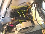
Reference document is GF82.62-P-3106-01B
Now that we have the signals what do we do with them? Per the diagram below it seems all the entertainment and Remote Locking signals head for an amplifier.
![Image]()
Reference document GF82.62-P-0001A
![Image]()
Reference document GF82.62-p-3105-04A
The amplifier filters out the signals coming from the rear window antennas, selectively amplifies them and sends them out via coax cable to their respective control modules. For AM/FM/TV they go to the Radio or COMAND. For Remote Unlock the key fob signal goes to Overhead Control Panel Control Module.
Some basic troubleshooting ideas:
Some reception, but its pretty weak---- That would indicate that COMAND / radio and antennas are working, but the amplifier isnt passing a strong enough signal. That MAY be due to bad amplifier, poor contact between antenna and amplifier or having a metallic tint applied to the rear window glass. The in glass antennas don’t have a “hardwired” connection to the amplifier. Note the small contact points at the end of each of the arms. That’s what connects to the appropriate antennas in the back glass. (Shown upside down). Anytime you have a “touch” connection you can have gunk ( for lack of a better term ) build up that can degrade that connection.
![Image]()
No reception at all, including key fob unlock ---- No voltage getting to amplifier (check fuse 61 in rear fuse box) means no connection from amplifier to antennas or amplifier has suffered a total meltdown.
And that about covers the in-glass antennas. Next up is the GPS antenna.
Hopefully staying on the correct side of “fair use,” I use diagrams from the WIS, but the verbal descriptions are mine. Mindful of copyright, it will be necessary to refer to the WIS for the more detailed descriptions and technical information provided by MB. To make that easier, I have cited the document numbers so that you can check the WIS for different option codes, model years, and greater detail. You can access the WIS by subscription (annual or daily) at STAR TekInfo
Lets begin... RF signals are picked up by an antenna, In the W220 antenna for FM, TV, AM and Remote Central Locking (your key fob) are embedded in the rear glass. All rear windows have the same antennas embedded regardless of country code. There are some minor shape variations between infrared shielded glass and normal glass but both types are functionally equivalent. In the first diagram below, Locations marked 1 are for the FM bands, for Remote central Locking, and for TV (the tuners were available in Europe only). Location 2 is for AM. Location 3 is actually the sharkfin antenna on the roof; it is not in the glass. Location 4 is for digital audio broadcasts, an option offered only in Germany.
The sharkfin (on the roof) serves to receive and transmit signals when a portable cell phone is plugged in to the system via a cradle (including hybrid Bluetooth cradles that have antenna couplers built in). It also transmits Tele-Aid signals, and may transmit and receive signals for the European UHI system. In North America, most modern portable cell phones do not use the sharkfin or rear bumper antenna, but rely only on the handset’s antenna.
GPS signals are received and passed from the (powered) GPS shark fin antenna to a splitter and on to COMAND; the split incoming signal is also passed to the Tele-Aid module. The shark fin is not part of the rear glass but is attached to it.
Note that the cell phone antenna is both receive and transmit; the others are receive only. In addition, power is delivered to powered antennas in two ways: By separate copper power leads, or via the coaxial cables, which may handle both RF signals and power.
There is a backup/spare TELEAID antenna located in the rear bumper but is not used unless the primary “sharkfin” is defective, as in a rollover. The telecommunication control unit (N112) detects a failure in the sharkfin antenna (A2/49a1) and activates the bumper antennas. Reference document GF82.95-P-3001SZ for specific details.
Reference document is GF82.62-P-3106-01B
Now that we have the signals what do we do with them? Per the diagram below it seems all the entertainment and Remote Locking signals head for an amplifier.

Reference document GF82.62-P-0001A

Reference document GF82.62-p-3105-04A
The amplifier filters out the signals coming from the rear window antennas, selectively amplifies them and sends them out via coax cable to their respective control modules. For AM/FM/TV they go to the Radio or COMAND. For Remote Unlock the key fob signal goes to Overhead Control Panel Control Module.
Some basic troubleshooting ideas:
Some reception, but its pretty weak---- That would indicate that COMAND / radio and antennas are working, but the amplifier isnt passing a strong enough signal. That MAY be due to bad amplifier, poor contact between antenna and amplifier or having a metallic tint applied to the rear window glass. The in glass antennas don’t have a “hardwired” connection to the amplifier. Note the small contact points at the end of each of the arms. That’s what connects to the appropriate antennas in the back glass. (Shown upside down). Anytime you have a “touch” connection you can have gunk ( for lack of a better term ) build up that can degrade that connection.
No reception at all, including key fob unlock ---- No voltage getting to amplifier (check fuse 61 in rear fuse box) means no connection from amplifier to antennas or amplifier has suffered a total meltdown.
And that about covers the in-glass antennas. Next up is the GPS antenna.