Mercedes-Benz Forum banner

A/C TROUBLESHOOTING - WITHOUT MBZ's SDS

1 reading
1.1K views 50 replies 10 participants last post by  jantonioriveranevare  
#1 · (Edited)
I own a 22 years old SL500. After 3 years without A/C, I decided to face this problem head on.

I've done some basic reading on how the A/C works and on how to troubleshoot it before I take it to MBZ.

After replacing all 6 seals in my A/C pressure measuring hoses and calibrated my needles to read 0 psi at atmospheric pressure, I measured STATICALLY (i.e., engine off and cool) the HI & LOW ports at an ambient temp of 96°F:

Hi: 50 psi
Low: 49 psi

As the Hi and Low sides are in equilibrium during this STATIC MEASUREMENT, both Hi and Low pressurea must be similar, as they are, but CERTAINLY both are WAY LOW in pressure. [Note: if there is a MBZ table for the 2003 SL500 R230.475 of what to expect when measuring HI & LOW ports pressures statically, please share it with us].

VACUUM TESTING: after evacuating the system with a pump I got in autozone and after 24 hrs of observation, I got no change whatsover in my HI & LOW PORT pressures: both stood at -30 inHg.

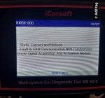
Instead of adding new R134a, I have opted to buy a new REFRIGERATOR PRESSURE/TEMP SWITCH. Why: my iCarsoft scanner reports "historic and actual" high pressures. So in lieu of my gauge readings and scanner report, this switch's pressure sensing function is damaged. I'll be replacing the cabin temp sensor, as it is cheap. The coolant temp sensor is working fine.

HELP: If any of you knows of other sensor important to A/C operation I have overlooked for this 22-years old car, please, please, let me know.

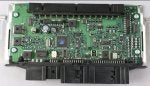
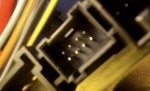
BLOWER/REGULATOR'S harness (4 FEMALE PINS) tested for ground PIN 1) , Bat+ (PIN 3) Signal from the FAN VELICITY knob (PIN 4) and the VOLTAGE REGULATOR INPUT to the BLOWER'S WINDINGS (PIN 2). Hopefully, I got this right.

CLIMATE CONTROL TEST RESULT: THE FAN VELOCITY KNOB FUNCTIONING is damaged, as the expected voltage response in PIN 4 as one moves the fan speed from low to medium to high fan-speed is erratic.

NOTE: BEFORE checking the FAN VELOCITY KNOB at LOW/MEDIUM/HIGH, I bench tested continuity between the terminals of the blower motor, so the motor should be fine. As the car has only 64K miles, I ASSume the other components within the blower motor are fine.

I have not tested the THERMOSTAT controls for now and ASSume that both are operational.

In sum, after a nice vacumm check, I will go ahead and buy the REFRIGERANT PRESSURE & TEMP SENSOR SWITCH and the CABIN TEMP SENSOR before recharching with R134a to do further testing, if required. Note: never forget to bring both ports of the A/C system to ATMOSPHERIC PRESSURE before uncrewing the refrigerant gas pressure/temp switch!!

A/C SYSTEM LAYOUT DIAGRAM FOR THE 2003 SL500 R230.475: a pdf or photo of it will be greatly appreciated.

I will update as I go and count on your assistance, as for sure, I'll get stuck somewhere along the way.

The photos below show: REFRIGERANT PRESSURE/TEMPERATURE SWITCH and the smaller CABIN TEMPERATURE SENSOR.

The table shown was used to establish that the A/C system was very low on R134a refrigerant.

Cheers !
 

Attachments

#38 ·
At present, with the engine temperature in equilibrium with the ambient temperature, which is 87 °F, the gauges read ca. 110 psi in both ports, as shown in the picture below.

Chat GPT suggests that as long as there is liquid in a can of R134a, the pressure of R134a in the gas phase will be a function of the ambient temperature the can is in equilibrium with. So, as at 87 °F (my current ambient temp), ChatGPT reports that gas can#1 should have a saturation head pressure over the liquid of 92-98 psig. So, it kind of makes sense why gas stopped flowing; the pressure inside the can is not enough to drive more gas into the sistem. So, STATICALLY, I guess it is impossible to empty a gas can completely. If I inverted the can upside down above the engine, would all the liquid left of R134a flow into the system? Please, answer this one for me!!
What if you raise the temperature of the can? Won't the pressure of the freon in the can go up?

Once your static pressure of 110psi is reached, it's not going to go higher with more freon.
The system with 920g will still read the 110 psi static pressure. That's why the static pressure doesn't tell you if you have the right amount in there, it only tells you if you have enough in there. Thats why it's important to know the weight of the freon going in and not the pressure. Putting the can in warm/hot water raises the pressure in the can, so you should be able to put more in there quicker. (Maybe you didn't have the water hot enough?)
It doesn't really matter, 1 can should probably be enough to raise it above the required 33psi to start the compressor.
I would just rather put in as much as I can before starting the engine.
I don't know, but I have read that you don't want to turn the can upside down as liquid may enter the line. It could damage the compressor as it can only compress gas and not liquid.
 
#39 ·
The EVAP temp sensor is a common failure point, and I would replace that.

The climate control module can be problematic, but they’re awfully expensive.

If you only got 230 g in there, that’s not nearly enough to have the system even operate. The capacity is closer to 900 g. And it needs to be within maybe two or 300 g of stated capacity in order for it to operate correctly.

Until you get the correct amount of Freon in there, any other troubleshooting is really moot.

if you’re filling out of those little 12 ounce cans, that’s an expensive way to do it. But, you can do it that way, and the way to get more Freon in there is to simply warm the can with a heat gun so that it’s not in liquid form.

Finally, and I mean this, sincerely, I almost replaced the climate control module on mine after refilling it properly, and checking all the pressure sensors with SDS, being unable to determine why the AC did not work correctly.

The problem turned out to be the consumer battery. The car had been parked for a while. The battery had gone flat, and I recharged it and restarted it. And then the AC started to act up. I knew they were correlated, but I certainly didn’t understand that they were causal.

So, I ended up fixing my AC by replacing the consumer battery with a new one. It’s been good ever since.

I’m not saying that that is definitively your problem, but in my case that was the fix
 
#41 · (Edited)
Thanks for responding, Astro14.

I was able to add 253 g of R134a into the system. I replaced the Evaporator Temperature sensor, as you suggested. The battery is just 6 months old and I monitor its health with an electronic device I bought.

Regarding the R134a recharging, STATICALLY, by warming the can with hot water, one has to be carefull, as the can may explode if one heats the can and the pressure inside it exceeds the critical can rupture pressure. I don't think hot water bsthing the R134a may cause that. I'll see if the can has a critical pressure listed on it above which it is dangerous to heat the can any further.

Well, excellent weekend, and thanks for your input.

Cheers !!
 
#40 · (Edited)
Hi Marko69, thanks for responding.

I put the can in "hot water" and pushed STATICALLY as much R134a gss as possible, but once there were no noticeable change at the gauges, both HI & LOW, I decided to stop. I only added 253 g. Until I have the compressor activated by either the FL SAM or the ACCCU, it will not start.

I am under the believe that the compressor won't start until the "implausible reading of -128 Bar" issue is solved. I may increase the STATIC PRESSURE in the system by just idling the car for a while, but it seems to me that the FL SAM is not processing well the Pressure switch analogue signal; the same applies to the Ambient Temp. sensor ( - 128°C). I have demonstrated that these sensors and their wiring are intact.

I am now looking more closely at the FL SAM's PWM signal OUTPUT which drives the ACCCU fan speed based on inputs such as Ambient Air Temp, Cabin Air Temp sensor, refrigerant gas pressure, etc.

I bought an used FL SAM for its PCB componets, relays/fuses, and use it to learn about its architecture and functioning ($54).

I will buy on monday a FL SAM which has all, PART#, HW# and SW# identical to my currently installed FL SAM, just in case it all boils down to a SAM I can't fix myself.

See photo of a typical FL SAM's PCB. I am currently learning about what the component known as a MOSFET does. I see six of them on this board.

Have an excellent weekend.

Cheers !
 

Attachments

#42 ·
One of the first things I fixed on my 05 SL500 was the A/C.
A/C red light was on which kept the variable speed compressor from running.
No clutch on this model again it's a variable speed pump.
With my scanner I was able to turn on the compressor/pump.
This allowed me to add refrigerant into the low side of the system.
Maybe 1 pound if I remember correctly and haven't had a issue since.
 
#43 · (Edited)
Thanks for responding, VTP499.

Indeed, when I first press the A/C conttol button, its red LED blinks 3 times and then stays on. I've been troubleshooting the cause methodically, but progress is slow, as I like to read up to prepare when testing any given area.

My iCarsoft MB V2.0 does not allow me to power the A/C myself. What scanner did you use to actuate the compressor?

Could I directly provide Bat+ and Ground to the terminals on it to turn it on? I understand that it receives PWM modulation signal from the ACCCU, as it is a variable speed compressor, as you highlighted. I'd like to turn it on for just a min or so to see if it is functional, as it's been 5 years since the A/C system stopped functioning.

Today, I'll be backprobing the PWM signal wire the FL SAM is sending to the ACCCU to see if the signal is in fact modulated or just constant voltage or 0 voltage, as well as any assiciated ground connection at the ACCCU.

Your guidance is appreciated.

Cheers !
 
#44 ·
Don't take this the wrong way, but this thread has gone totally off the rails.

First of all, you need to scan the AAC module and see what codes you have. I know that you said in an an early post that your scanner won't read climate control, but I am 95% certain that the icarsoft MB 2.0 will read that module. Sometimes there can be a connection issue for specific modules, but your first step is to figure out why the AAC module is shutting down the compressor. It is probably low pressure, but there is no point in flying blind when the system will tell you what the actual problem is.

Secondly, literally everything you got from chatGPT is wrong. Just delete it.

Third, you need to know that there is a difference between the SAM and the fuse block. Connector M2 on the fuse block is NOT the SAM connector 2. The 4 SAM connectors are at the very bottom of the assembly. Plug 1 is the 6 pin plug with wide pins and they go across from there (2,3,4). The B14 outside temp sensor goes to pins 3 & 14 on plug 3. B12/2, a/c pressure/temp sensor goes to pins 2, 4, 5, & 15 on the same plug. The A/C compressor (a9) control line is pin 13 on plug 3. Also, the A/C blower is controlled directly by the AAC control, not either front SAM. A/C compressor is ultimately controlled by the drivers side SAM, but the calculation is done in the AAC and set to the SAM to output the correct voltage.

Fourth, you are wasting your time trying to recharge the system statically. I think the icarsoft will allow you to turn on the compressor, but if not, get a scanner that will or take it to someone who has the proper equipment.

Fifth, get a copy of WIS. Again, there is no point in flying blind. Get real information, not something that an AI bot makes up.
 
#45 · (Edited)
Thanks for responding, Mikej65.

I appreciate your comments.

Tomorrow, I will take screenshots of the iCarsoft MB V2.0 Air Conditioning System Function which I click on to obtain most of the A/C parameters I have shared with you all.

I understand the difference between the SAM and the fuse block above. There are 4 connectors at the botton of the SAM.

I stand corrected, Plug 1 has 6 females pins which connect to a cavity with 6 wide male pins. The other plugs are then labelled in consecutive order 2, 3, 4.

Using that convention then: the 2 wires of my Ambient Air Temp Sensor and the 4 wires of the Gas Pressure Switch connect to Plug#3. This is in agrrement with your information. I traced them there from the sensors' wires themselves: all 6 are nominal. There is no Plug #2 connected to its respective cavity. I looked very well for a connector but there is none.

Anyways, to recapitulate:

1. Plug #3:

Pins# 3 & 14: Ambient Air Temp Sensors
Actual Colors: One wire green. The other brown/green.

Pins# 2,4,5 & 15: Gas Pressure Switch
Actual colors: yellow, yellow/gray, blue/green and brown/gray. I need to assign the correct wire color to its pin#.

Pin# 13: A/C compressor control line.
Question: is this wire the line that sends PWM to the Compressor's Solenoid Control Valve?

2. Only the ACCCU controls the REG/BLOWER unit.

3. Only FL SAM Drivers control the A/C compressor performance based on input it receives from the ACCCU.

4. I will definetively look well into my iCarsoft scanner and even call them to know for sure if the scanner can or cannot activate the compressor. I'll do that tomorrow.

5. I will certainly get a copy of the WIS manual. How does one get a manual. Is it a paper manual? or a read-only CD?

Note: by the way, today I received a new Reg; the blower is soon to follow.

Another possibility why the conpressor will not start, the REG/BLOWER are trash, as per my bench testing. Hopefully, replacing the REG/BLOWER will certainly help to eliminate one possible cause, as when no air flows by the evaporator, it leads to R134a slugging, freezzing, poor heat exchange, and ultimately compressor shutdown. So, to prevent that the compressor is kept off.

It is my contention that the compressor will not start for this other reason, the ACCCU is reading implaussible pressure (i.e. - 128 Bars), as well as implaussible Ambient Air Temp (-128 °C); that is why I have worked so hard to eliminate the two above sensors and their wiring as causes.

I believe that no matter how much R134a you put in the system (I have 100 psi in the LOW SIDE; more than 33 psi to get it going), but the A/C is locked into stagnation because of the implaussible sensor results. That's why I have probed the wiring in these two sensors and they are nominal. The sensors too are nominal.

UPDATE: WHAT I DID TODAY. A NEW FINDING

With the IGNITION ON (A/C System Off), I backprobed the 4 wires of the Gas Pressure Switch.

Results for each wire:

1. Brown/Gray to clean local Ground next to the FL SAM: + 4.13 V (steady). Will try Bat - too as ground tomorrow to confirm.

2. Yellow/Gray to Brown/Gray: -0.036 V (steady)

3. Blue/Green to Brown/Gray: 0.453 V (steady)

4. Yellow to Yellow/Gray: -0.238 V to - 1 V fluctuating

As per MBZ convention, the Brown/Gray wire must be the sensor's ground. Would you check that for me MikeJ65?

If that wire is indeed the pressure sensor's ground, my implaussible pressure reading might be due to a "FLOATING GROUND".

Question, MikeJ69:

Is the pressure sensor's ground created by the FL SAM? or is it provided by the metal the sensor screws into? Given that the wiring, plug and male pins in FL SAM lcavity #3 look nominal, I tend to believe that we might also have a FL SAM issue.

I'll repeat tomorrow what I did today to be certain.

Below, photos of the Gas Pressure Switch.

Thanks for your patience and I will get back to you with all the deliverables I highlited above.

Cheers
 
#46 · (Edited)
UPDATE:

1. After talking to iCarsoft this morning, my MB V2.0 scanner does not activate the A/C compressor. I can't even upgrade the software to do so.

I will buy iCarsoft V3.0

MikeJ69, could I unplug the two-wire plug from the compressor, and power the two pins on the compressoer with a car BATTERY?

2. Just learned that a "FLOATING GROUND" is not necessarily a bad ground. The FL SAM is creating a "FLOATING GROUND" to minimize noise/interference from blower motor and the like in order to have a clean R134a gas pressure/temperature sensor signals for further processing by the FL SAM.

Cheers !
 
#47 ·
As far as WIS, there are a couple of options. The cheapest option is to buy a USB drive or download from ebay. However, I would also consider getting an SSD that has WIS plus Xentry software. Even without the hardware to run Xentry, you can run in sim mode and get a LOT of trouble shooting information. It will suggest tests to determine, for example, if a sensor, wiring, or module is the cause of a DTC. You can get an SSD from ebay or aliexpress. WIS generally comes with EPC, which is the parts catalog and will give you exact part numbers based on your VIN.

For the pressure sensor, yes the pin 5 brown/gray wire is the sensor ground. it might float some from chassis ground, but 4.13V seems way excessive. The proper test is to first remove the #3 connector, then check for 5V reference power between pins 4 & 15 on the SAM module pins. Tolerance is +/- .25V. While you have the connector off, check resistance between pins 2 & 5 in the socket. This is the temperature thermistor and should have resistance of 10.5-15.5k at 20C and 4.5-6.5k at 40C. Note that the temperature sensor was dropped as of 5/2005 and it is very possible that revised AAC software is not using this sensor. Finally, plug the connector back in and backprobe pins 4 & 5. This is the pressure signal and should be between .4 and 4.6V depending on the pressure.

To test the ambient temperature sensor, remove the connector and test resistance between pins 3 & 14 in the connector. Resistance should be 3-4.5k at 20C ambient and 2-3k at 30C.

Yes, pin 13 is the PWM signal for the A/C compressor.
 
#48 ·
Just found these three files at the MBZ Forum:

The Refrigerant Gas Pressure/Temp Switch (B12) is shown to have 3 wires, whereas mine has 4 wires.

My car: 2003 SL500 R230.475 5G-Tronic 722.6
 

Attachments

#50 · (Edited)
UPDATE:

MikeJ69,

The only way I could get access to connector/plug #3 to do the testing was by UNPLUGING the three plugs at the very posterior top edge of the FL SAM, whose wires I hold in the photo below.

They seem to be power wires, a ground (black wire) and a yellow wire (?). Would unplugging them made my readings invalid?

I then disconnected plugs 1, 3 & 4 to be able to lift the FL SAM even more to fix it in place with a wire so it would not fell on my working hands. Only then could I handle with boths hands connector 3 to do the testing:

1. Connector 3 unplugged, ignition on: Gas Pressure/Temp Switch

PIN 4 to PIN 15: Started at 0.06V and settled at 0.108 V (Ref. 5V +/_ 0.25V).


2. Connector 3: Ambient Air Temp. sensor

PIN 2 to PIN 5 (Brown/Gray): 7.46 KOhms
@ 34°C. What's the Ref. value @ this temp.?

3. Connector 3: Backprobing with Ignition ON to look for the Gas Pressure/Temp Switch's Signal Reference value

PIN4 to PIN5: N/D
(Ref. 0.4-4.6V)

It was technically impossible to backprobe the wires for PIN4 & PIN5 with the connector plugged. I was afraid I would rip the harness off.

Also having the 3 aforementioned plugs at the posterior edge of the Fuse Block disconnected made me realize that all these measurements might not be accurate after all.

I'll look at it tomorrow again and see if there is a way to be able to do this.

I never lose hope.

Cheers !
 

Attachments

#51 · (Edited)
UPDATE:

The only way I could get access to connector/plug #3 to do the testing was by UNPLUGING the three plugs at the very posterior top edge of the FL SAM, whose wires I hold in the photo below. They seem to be power wires.

I then disconnected plugs 1, 3 & 4 to be able to lift the FL SAM even more and be able to fix it in place with a wire so it would not fall on my working hands. Only then could I handle connector 3 to do the testing:

1. Connector 3 unplugged, ignition on: Gas Refrigerant Pressure/Temp Switch:

PIN 4 to PIN 15: Started at 0.06V and settled at 0.108 V (Ref. 5V +/_ 0.25V).

2. Connector 3 unplugged, ignition on: Ambient Air Temp. sensor

PIN 2 to PIN 5 (Brown/Gray): 7.46 KOhms
@ 34°C.

3. Connector 3 connected: Gas Pressure/Temp Sensor's Signal Backprobing

PIN4 to PIN5: N/D

Unable to reach the wires to backprobed with all the connectors plugged in.

Note: the first 2 measurements I made by unplugging 3 plugs at the back of the fuseblock, which I show by grabing the wires in the photo below. This made me reconsider the accuracy of my measurements.

I'll try again tomorrow to see if there is a way to do this without riping the wires off their plugs.

To end this on a good note: even though I was not able to backprobed the refrigerant pressure switch today, my iCarsoft MB V2.0 reported accurately today that the Refrigerant Gas pressure is too low, which is indeed the case as there is only 253 g of R134a within the system ( see photo); though at current temps it should be around 100 psi. However, never before the scanner reported low gas pressures; it always reported high refrigerant gas pressures.

Also, there seems to be a CAN problem where the FL SAM, or part of it, seems no to be communicating with, I presume, the ECU (car's main computer). See DTC below! I'll start reading up on this DTC.

Thanks again for your assistance, MikeJ69.

Cheers !
 

Attachments