Mercedes-Benz Forum banner

2000 E320 K40 relay (or is it???)

36K views 49 replies 7 participants last post by  Deplore  
#1 ·
I've been looking into an issue with my father-in-law's 2000 E320 that started this Sunday, June 11. We had driven the car without any issues in the morning and early afternoon, but in the late afternoon after making a stop and removing the key from the ignition, we were unable to get it started back up. There weren't any signs that something was about to go wrong as far as I know. If it's relevant, the atmospheric conditions were a temperature of 83F and humidity of 44%.

We are able to unlock the car normally with the key fob. When we put the fob into the ignition and turn it to the on position, all cabin electronics come on and operate normally. When we turn the key to the ignition position, however, we can't hear any of the normal responses we'd expect from the engine - starter motor or engine crank. However, from inside the engine compartment, we can hear a few brief clicking sounds.

We've tested the battery - it shows 12.6 volts when the car is inactive, and 12.3 volts when the ignition is in the on position with electronics running. There is no voltage change at the battery when we turn the key to ignition.

One of the suggestions I found in this forum to fix this and a variety of other issues with W210 cars was to remove the K40, redo the solder points on the PCB, and replace. I want to try this repair as a first step, since it doesn't cost anything.

I found what appeared to be the right compartment in the engine - it was on the right hand (passenger) side of the car, marked with an air conditioner label. It was covered by a plastic top with four captive phillips screws. Inside the compartment were three computer-ish looking devices, plus what appeared to be a fuse box with lots of cables coming out. However, when I had disconnected the cables and removed the box, the relay looked significantly different than the ones I had seen on various YouTube videos and photos I found online.

This is what I was expecting: external link to large image


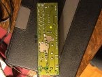
But what I found looked quite different:

From the top:


From the bottom:


There were also far more cables attached to the top than I was expecting. Not sure if I removed the wrong part, or if it's just a different version on this particular model. I've also seen some other people mention that there are *two* K40's, and the other is on the other side of the engine compartment. But I don't see anything that fits that description over there, just the main fuse box (unless it's hidden under the back of the fuse box).

Any idea if what I'm looking at is the right part, or if I should be looking elsewhere? I just want to make sure it's right before I go resoldering anything.

Thanks!
 
#2 · (Edited)
Hello :)

The fuse panel you show in the picture is for the 1998+ E320 cars and the one in the external link is for older models.

The older fusepanels had soldering PCB track cracking issues, and the newer ones do not seem so suffer from this as such.

There is another K40 relay / fuse panel at the driver's side (which is called K40/2) which is not relevant at this point.

1) With the above fuse panel installed, the first things I would check are the fuses, especially the the 10 amp fuses, and the voltages on them with the ignition switch in "run" position. This would make sure you get the power to the engine computer, and transmission computer.

2) Then, have someone turn the key to start the car and listen to the black relay that looks like a big ice cube on the K40 module next to the 40 amp orange fuse. If you hear the a click, and the starter does not turn, then you either have a bad starter relay, or bad starter / starter wiring. If you do not hear a click, You may have a problem with the electronics or switches (can you shift between gears with the ignition ON ? Try starting in Neutral, and move the shifter between gears several times, and re-try in P and / or N). If the start is not "enabled" by the engine computer, your car will not start.

3) With the key OUT, remove the starter relay, and put a jumper wire across the relay contact terminals on the receptacle on the K40. Terminals A and C, marked as circuit 30 and 87.

4) With the jumper installed on the K40 relay board, insert the key and turn briefly to "run". If the starter engages, turn and remove the key immediately. You have a bad starter relay, or wiring / connector between the starter and the relay.

5) If the starter does not engage from 4), then have the starter / wiring checked. Few posts similar to yours had problems with the starter wiring damage (between the starter solenoid and the starter motor) due to corrosion.

You can check this link for generalized start issues.

http://www.mercedesmedic.com/mercedes-wont-start/
 
#3 ·
Thanks very much for your reply! I will try these tests when I get home tonight.

Also, I just found this thread... seems to be fairly similar symptoms to what I've seen, and it's the same year and model:

http://www.benzworld.org/forums/w210-e-class/1690450-00-e320-wont-start.html

Hello :)

The fuse panel you show in the picture is for the 1998+ E320 cars and the one in the external link is for older models.

The older fusepanels had soldering PCB track cracking issues, and the newer ones do not seem so suffer from this as such.

There is another K40 relay / fuse panel at the driver's side (which is called K40/2) which is not relevant at this point.

1) With the above fuse panel installed, the first things I would check are the fuses, especially the the 10 amp fuses, and the voltages on them with the ignition switch in "run" position. This would make sure you get the power to the engine computer, and transmission computer.

2) Then, have someone turn the key to start the car and listen to the black relay that looks like a big ice cube on the K40 module next to the 40 amp orange fuse. If you hear the a click, and the starter does not turn, then you either have a bad starter relay, or bad starter / starter wiring. If you do not hear a click, You may have a problem with the electronics or switches (can you shift between gears with the ignition ON ? Try starting in Neutral, and move the shifter between gears several times, and re-try in P and / or N). If the start is not "enabled" by the engine computer, your car will not start.

3) With the key OUT, remove the starter relay, and put a jumper wire across the relay contact terminals on the receptacle on the K40. These terminals are parallel to each other, NOT those that form a "T". The T contacts are the coil side which are connected to the engine computer.

4) With the jumper installed on the K40 relay board, insert the key and turn briefly to "run". If the starter engages, turn and remove the key immediately. You have a bad starter relay, or wiring / connector between the starter and the relay.

5) If the starter does not engage from 4), then have the starter / wiring checked. Few posts similar to yours had problems with the starter wiring damage (between the starter solenoid and the starter motor) due to corrosion.
 
#8 ·
Results

To answer your testing steps:

1) All fuses in the K40 box tested 12.2v EXCEPT for the big orange 40amp one, which had zero voltage. All fuses tested ok for resistance.

2) Definitely no sound coming from the black cube/relay when attempting to start. There are, however, other sounds (cicks and buzzes) that come from the engine during this time. I had a helper turn the key gradually through the positions and made note of the under-the-hood noises at each one:

Begin:

  1. Insert to position 0: light "chunk" sound from key receptacle when the key is inserted and engages
  2. Turn 1 right to position 1: no sound
  3. Turn 1 more right to position 2: no sound
  4. Turn 1 more right to position 3, and hold: first a loud double click, and almost concurrently a loud buzzing starts, followed one second later by a softer single click. The buzzing sound continues.
  5. Release from position 3 and return to position 2: The loud buzzing sound that started when first turning to position 3 continues during position 2
  6. Turn 1 to left back to position 1: Buzzing sound from position 3 stops
  7. Turn 1 to left back to position 0: No sounds stop or start
  8. Remove key: Light "chunk" sound from key receptacle as key is removed

End

2 (continued) When I hold the key in position 3 (start), I am able to shift through gears from Park through Drive several times. I see the indicator on the dashboard change. I also confirm that the car remains stationary except when I shift to neutral, at which point it rolls.

3+4) Not sure if I should have continued at this point, but I found a short braided copper wire and used it to jumper the specified points after removing the relay. No change in anything with this setup.

Can we draw any conclusions based on the information above, or are there further things to try?
 
#10 ·
To answer your testing steps:

1) All fuses in the K40 box tested 12.2v EXCEPT for the big orange 40amp one, which had zero voltage. All fuses tested ok for resistance.

2) Definitely no sound coming from the black cube/relay when attempting to start. There are, however, other sounds (cicks and buzzes) that come from the engine during this time. I had a helper turn the key gradually through the positions and made note of the under-the-hood noises at each one:

Begin:

  1. Insert to position 0: light "chunk" sound from key receptacle when the key is inserted and engages
  2. Turn 1 right to position 1: no sound
  3. Turn 1 more right to position 2: no sound
  4. Turn 1 more right to position 3, and hold: first a loud double click, and almost concurrently a loud buzzing starts, followed one second later by a softer single click. The buzzing sound continues.
  5. Release from position 3 and return to position 2: The loud buzzing sound that started when first turning to position 3 continues during position 2
  6. Turn 1 to left back to position 1: Buzzing sound from position 3 stops
  7. Turn 1 to left back to position 0: No sounds stop or start
  8. Remove key: Light "chunk" sound from key receptacle as key is removed

End

2 (continued) When I hold the key in position 3 (start), I am able to shift through gears from Park through Drive several times. I see the indicator on the dashboard change. I also confirm that the car remains stationary except when I shift to neutral, at which point it rolls.

3+4) Not sure if I should have continued at this point, but I found a short braided copper wire and used it to jumper the specified points after removing the relay. No change in anything with this setup.

Can we draw any conclusions based on the information above, or are there further things to try?

Great observations:)

1) your key unlocks the steering wheel and turns, so your ignition is properly authorized.
2) you can shift the gear selector and observe the correct gear indication, so your transmission computer is powered up and can register the brake switch and the gear shifter module signals. So you should have start enabled.
3) You removed the black relay (key out), and put a jumper on the RIGHT set of contact sockets on the K40 module (marked as 30 and 87 which are the terminals for the relay switch side, NOT the coil side) see picture attached. After you did this with gear in Park, you inserted the key and put it in run position for 5 seconds, and nothing happened (no crank).

Based on the above, I would just make sure that the relay switch itself gets 12V from the ignition switch when the key is in run position. With the relay out, measure the voltage between the terminals that you previously put the jumpered. You should read 12V (with key in run). If you do not, then there is a problem with the ignition switch contacts that is supposed to provide this voltage when you turn the key (circuit 15u). If you read 12V, and jumpering does not work, you then have a confirmed problem with the starter or wiring to the starter or wiring between the starter motor and the solenoid (mounted on the starter).

When the engine module fan fails, it typically blows one of the 10 amp fuses out which is shared with the transmission control module. You checked the fuses and the voltages on the fuses and they seem to be fine. The 40 amp fuse is for the air injection pump, and will have voltage on it when the engine actually starts, so no problem there.
 

Attachments

#12 ·
Check my edited text regarding the relay terminals. I tried to find a picture of the relay contacts and the best way is to look at relay side or bottom. It should be between 30 and 87. After you jumper the relay terminals, you insert the key and turn the key to run, not start. When you turn the key to run, the ignition is supposed to apply 12V to terminal 30 and with the jumper, it should apply power to the solenoid relay.

No need to check the steering wheel lock. When you insert the key, the ignition switch (EIS) first releases the steering lock (ESL). Upon acknowledgement from ESL, then released the lock on the ignition itself and this allows you to turn the key. If your key turns, the steering is unlocked.
 
#13 ·
6/17/2017 Relay Diagnosis

​Measuring voltage with relay removed:
  • Voltage measured between terminal 30 and 87 was 7.62
  • Voltage measured between terminal 30 and ground was 11.88 (this is the same voltage measured across all the fuses)
  • Voltage measured between terminal 87 and ground was 4.20

I re-did the jumpering, this time jumpering from terminal 30 to 87. Still no effect when turning the key to position 2 (run).

Out of curiosity, I measured the voltage between the jumper wire and ground, and it was 11.88.

The voltage measured at the battery has been going down since I've been using electronics and not running the alternator. It was previously around 12.2 when the car was running, and today it was 11.88.

I'm charging the battery back up and I'm going to try the jumpering operation again on the suspicion that maybe the voltage from the battery was insufficient.

Also, here is a link to a recording I made of the engine sounds when trying to start the car:
Engine Sound Sample

Let me know if anyone has other thoughts or suggestions.
 
#14 ·
OKAY. After I posted that, I realized that I did the jumper wrong AGAIN and also measured voltage across the wrong terminals.
So... I did it AGAIN just now, and here are the new measurements:

6/17/2017 Relay Diagnosis
Measuring voltage with relay removed:
Voltage measured between terminal 30 and 87 was 12.36
Voltage measured between terminal 30 and ground was 12.35
Voltage measured between terminal 87 and ground was 0
I re-re-did the jumpering, this time REALLY jumpering from terminal 30 to 87. Still no effect when turning the key to position 2 (run).

​Measuring voltage with relay removed:
  • Voltage measured between terminal 30 and 87 was 7.62
  • Voltage measured between terminal 30 and ground was 11.88 (this is the same voltage measured across all the fuses)
  • Voltage measured between terminal 87 and ground was 4.20

I re-did the jumpering, this time jumpering from terminal 30 to 87. Still no effect when turning the key to position 2 (run).

Out of curiosity, I measured the voltage between the jumper wire and ground, and it was 11.88.

The voltage measured at the battery has been going down since I've been using electronics and not running the alternator. It was previously around 12.2 when the car was running, and today it was 11.88.

I'm charging the battery back up and I'm going to try the jumpering operation again on the suspicion that maybe the voltage from the battery was insufficient.

Also, here is a link to a recording I made of the engine sounds when trying to start the car:
Engine Sound Sample

Let me know if anyone has other thoughts or suggestions.
 
#15 · (Edited)
If you look at the diagram I sent you, circuit 30 is the ignition switch side and 87 is the starter solenoid side. From the measurements you did , I suspect that you have a problem with the starter, and the typical weak point is the braided wiring between the motor and the solenoid which gets corroded and disintegrate over time due to elements. If this is the problem, the solution is a new starter I am afraid.

With the relay out , NO JUMPER, and key out, you can measure the resistance between terminal 87 and chassis ground. It should be less than few ohms.

You can also apply fused (10 amp) battery voltage to terminal 87 (the violet side on the diagram. If the starter does not turn, you have a confirmed starter failure (or the connection between the relay terminal and the violet wire terminal (connection A1, pin 6 on the K40 relay module).

Regarding the buzzing sound, do not worry about it. My car does that too with the key turned. I think it comes from the throttle actuator motor, at least someone commented on it before).
 
#16 ·
What setting should I be using to measure resistance between terminal 87 and ground? I have 2000/200/20k ohm and 2000/200 ohm.

Also, how do I apply fused voltage? That's a term I am not familiar with.


With the relay out , NO JUMPER, and key out, you can measure the resistance between terminal 87 and chassis ground. It should be less than few ohms.

You can also apply fused (10 amp) battery voltage to terminal 87 (the violet side on the diagram. If the starter does not turn, you have a confirmed starter failure (or the connection between the relay terminal and the violet wire terminal (connection A1, pin 6 on the K40 relay module).
 
#19 ·
It's a fair question. For other people the answer would certainly be no, but for me the answer is yes. Other people also might not have asked beginner-level electronics questions (and attempted to Google them instead), but I felt pretty comfortable asking since the response thus far had been pretty positive. I'll likely be finished with this line of investigation soon, at which point I'll give my father-in-law the update and let him make the call as to how to proceed. He'd normally be working on it himself right now, but he's away at his summer cottage and had loaned me this car in the meantime.
 
#18 · (Edited)
Start with 2000 ohm setting. You could then switch to 200 ohms for better resolution. If the starter wiring is gone you will read an open circuit.

The resistance test should be sufficient at this point. You are nearly there. Just make sure you connect the multimeter between 87 and chassis ground, and tell us what the resistance is. Alternatively you could remove the connector marked as A1 from K40 module, and measure the resistance between pin 6 (violet wire) and the chassis ground.
 
#20 ·
I did a bit of extra reading on "how to use a multimeter":

https://www.ifixit.com/Guide/How+To+Use+A+Multimeter/25632#s65007 iFixit said:
@If your multimeter reads close to zero, the range is set too high for a good measurement. Turn the dial to a lower setting. If you set the range too low, the multimeter simply reads 1 or OL, indicating that it is overloaded or out of range. This won't hurt the multimeter, but we need to set the dial to a higher range. The other possibility is that the circuit or component you are testing doesn't have continuity—that is, it has infinite resistance. A non continuous circuit will always read 1 or OL on a resistance test.;
In my case, I took readings at each range setting, and here's what I got:
2000kohms : 000
200kohms : 00.2
20kohms : 0.25
2000ohms : 255
200ohms : 1. (open loop)

So, based on the 2000 and 200 ohm readings, it would seem the resistance is very high or infinite, in other words an open circuit, in other words, the starter wiring is gone....

Start with 2000 ohm setting. You could then switch to 200 ohms for better resolution. If the starter wiring is gone you will read an open circuit.

...connect the multimeter between 87 and chassis ground, and tell us what the resistance is
 
#22 ·
It's also astonishingly easy, during jumper testing, to cause a lot of expensive damage, even using a fused source.

Good for you, you have a good idea of the problem now (starter, or wiring to the starter). I get nervous recommending "jumper this" to somebody who clearly hasn't had experience, when the alternate outcome can be . . . new <insert expensive part here> plus original problem.
 
#30 ·
Have you turned the ignition key to position 2 after you put the jumper between 30/87 ?

If you did, and no crank, you either have 12V supply issue to the relay contacts or problem with the wiring to the starter solenoid / or starter solenoid / starter.

With the key in position 2 measure voltage between socket 30 and chassis ground. You should have 12V. If you don't you have a supply issue to K40 from the ignition switch.

If you have 12V, then measure the resistance between the chassis ground and socket 87 (solenoid resistance). If open you have a wiring / solenoid issue. If close to short (few ohms) then the solenoid side is OK, but you may have a problem with the solenoid mechanics (not applying 12V from the battery to the starter.
 
#32 ·
Hi all, hope you guys don't mind me digging this thread up for another time. This thread has so far been the closest to a solution for me.

Same premise as the original posts back from 2017, but from the probing I did on the k40 relay block here is the results I get (and where I differ from the posts I've seen).

Voltage between 30 and 87: 11.5V
Resistance between 30 and 87: 250 ohms

Voltage between 30 to ground: 0V
Resistance between 30 to ground: 1.5 ohms

Voltage between 87 to ground: 11.5V
Resistance between 87 to ground: 246 ohms

Voltage to purple wire during key position 2 and 3: 10.5V (may be low because at this point I was keyed on quite a few times)

Resistance between 30 and purple wire: 0.5 ohms

So my interpretation of this means that:
1) My starter wiring is okay since the 87 side of the k40 relay is powered.
2) My ignition switch is okay since my purple wire is getting battery power (10.5+)

I'm making a big assumption here, but I'm assuming the purple wire and pin 30 should be connected. So does that mean that the issue is a connection within the k40 relay board? Not connecting the purple wire to pin 30? But then why is resistance and continuity there when testing between these 2 points?
 
#33 ·
Hi all, hope you guys don't mind me digging this thread up for another time. This thread has so far been the closest to a solution for me.

Same premise as the original posts back from 2017, but from the probing I did on the k40 relay block here is the results I get (and where I differ from the posts I've seen).

Voltage between 30 and 87: 11.5V
Resistance between 30 and 87: 250 ohms

Voltage between 30 to ground: 0V
Resistance between 30 to ground: 1.5 ohms

Voltage between 87 to ground: 11.5V
Resistance between 87 to ground: 246 ohms

Voltage to purple wire during key position 2 and 3: 10.5V (may be low because at this point I was keyed on quite a few times)

Resistance between 30 and purple wire: 0.5 ohms

So my interpretation of this means that:
1) My starter wiring is okay since the 87 side of the k40 relay is powered.
2) My ignition switch is okay since my purple wire is getting battery power (10.5+)

I'm making a big assumption here, but I'm assuming the purple wire and pin 30 should be connected. So does that mean that the issue is a connection within the k40 relay board? Not connecting the purple wire to pin 30? But then why is resistance and continuity there when testing between these 2 points?
Hello :)

Please specify the model and model year of your car.

Are you trying to read the resistances and voltages on the starter relay socket (with the really taken out and key in the pocket) ?
 
#34 ·
Oops sorry for the missing details.

2001 E55 AMG - so in my case, the only purple/violet wire i could find was one that was connected to the k40 relay module (not on the opposite side of the car like in the diagrams included earlier).

Voltages tested with key in position 2 (and occasionally in position 3 if i felt like there was a chance the circuit was tied only to the crank position). Resistances were measured in key position 2.
 
#35 ·
OK, how about looking at the diagram for the starter relay (K2 in the diagram) located on the K40 ?

First, never measure resistance when the circuit has power (which you did between 30 and 87 sockets with the relay removed when the key is in position 2 or 3). You will get nonsense results. With key in position 2/3, socket 30 will have the B+ (battery voltage). 87 is the starter solenoid side so you would be connecting the ohmmeter in series with the solenoid coil and the B+ source.

The easiest way is to put a jumper wire between 30 and 87 sockets on the starter relay socket WITH KEY OUT, then turn the key to position 2 momentarily (few seconds). The starter should spin. If it does, then the starter and the wiring is fine.

If the starter is not activated, then with key in pos 2, and jumper removed, you measure the VOLTAGE between 30 and chassis ground making sure it has B+, then you measure RESISTANCE between 87 and chassis ground. It should read close to a short (few ohms). That is the solenoid resistance.

If no B+ on 30 with key in pos 2, possible problem with K40, wiring to K40, ignition switch ....

If no low resistance between 87 and chassis ground, then problem with K40, wiring to the solenoid violet wire).

If both checks out OK , bad starter.

If the starter spins in the first test but the car does not crank with key in pos 3, then you need to look at the coil side of the relay, fuses, wiring ECU, ignition switch , authentication issues, transmission controller, shifter..........
 

Attachments

#36 ·
Ok so maybe i wasn't too stupid and just remembered my process incorrectly, I remeasured resistances with the key out, car off and got same numbers (new measurements below)
All key off:
30 to ground: 1.3 ohms
87 to ground: 248.5 ohms

Re-did the other testing too (followed the earlier posts on the jumper test) and here are the new results
Jumper on 30 and 87 - pos 2 - no start
Jumper removed - pos 2 - Pin 30 to ground, 0V
Resistance of 87 to ground - overload

So resistance of 87 to ground being shorted then sound correct if i'm interpreting your info corrrectly

The 0V from 30 to ground means that, obviously, I'm not getting power. but the questions is why and where does the power stop?
If I have 12V to the violet wire pin going into the module, then does that mean the issue is within the k40 module?
 
#37 · (Edited)
I have a feeling you are mixing 30 and 87.

Jumper on 30 and 87 - pos 2 - no start
Jumper removed - pos 2 - Pin 30 to ground, 0V
Resistance of 87 to ground - overload
What does overload mean in the last measurement ? And why are you measuring 248.5 ohms in one test and "overload" on the other ? With 87 to ground resistance measurement key position is not important with the relay / jumper removed. It is just the resistance of the solenoid coil of the starter plus wiring, and it is way too high.

In any case, look at the diagram I posted. 30 is supplied through Connector C pin 3 on the K40. Locate connector C (as marked) and pin 3 (PINK/RED colored wire). Either pierce wire or back probe pin 3 and measure the voltage between Pin 3 and chassis ground WITH key in pos 2). It should read B+. It comes from the ignition switch (through x63/6). It is supposed to carry battery voltage with ignition switch in pos 2/3).
 
#38 ·
With the orientation of pins 30 and 87 being different, and clearly marked on the relay itself, I don't believe I am mixing things up. But for a description, there are 3 blades that are horizontal, and 1 blade that is vertical. the 3 horizontal blades on the relay are marked 30(left/US passenger side as plugged in), 86(closest to front of car as plugged in), 85(closest to trunk as plugged in). The 1 vertical blade is marked 87(US driver side as plugged in)

Overload in my case means an open circuit (infinitely high resistance, or atleast a reading my multimeter can't read?), as probes touching each other result in low (0.1 ohm) value readings - so I was not correct (a correction to my last post)
But here is the behavior of the resistance and voltage on pin 87 to ground, all done in one go
Key off - ~250 ohms , 0V
Pos 1 - ~250 ohms , 0V
Pos 2 - Overload , 11.5V
Pos 3 - Overload , 11.5V


But just incase, I did this study on 30.
Key off - 1.3 ohms , 0V
Pos 1 - 1.3 ohms , 0V
Pos 2 - 1.3 ohms , 0V
Pos 3 - 1.3 ohms , 0V

Connector C Pin 3 - Pink/red stripe wire voltage behavior (back probe to ground)
key off - 0V
Pos 1 - 0V
Pos 2 - 11.5V
Pos 3 - 11.5V

Also, thank you so much for taking your time to walk through this issue with me.