Gabriel,
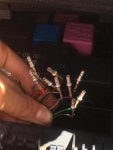
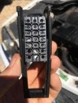
I have been in your shoes with the N10 module, and the removal of the connectors does not look logical anyone can figure out.
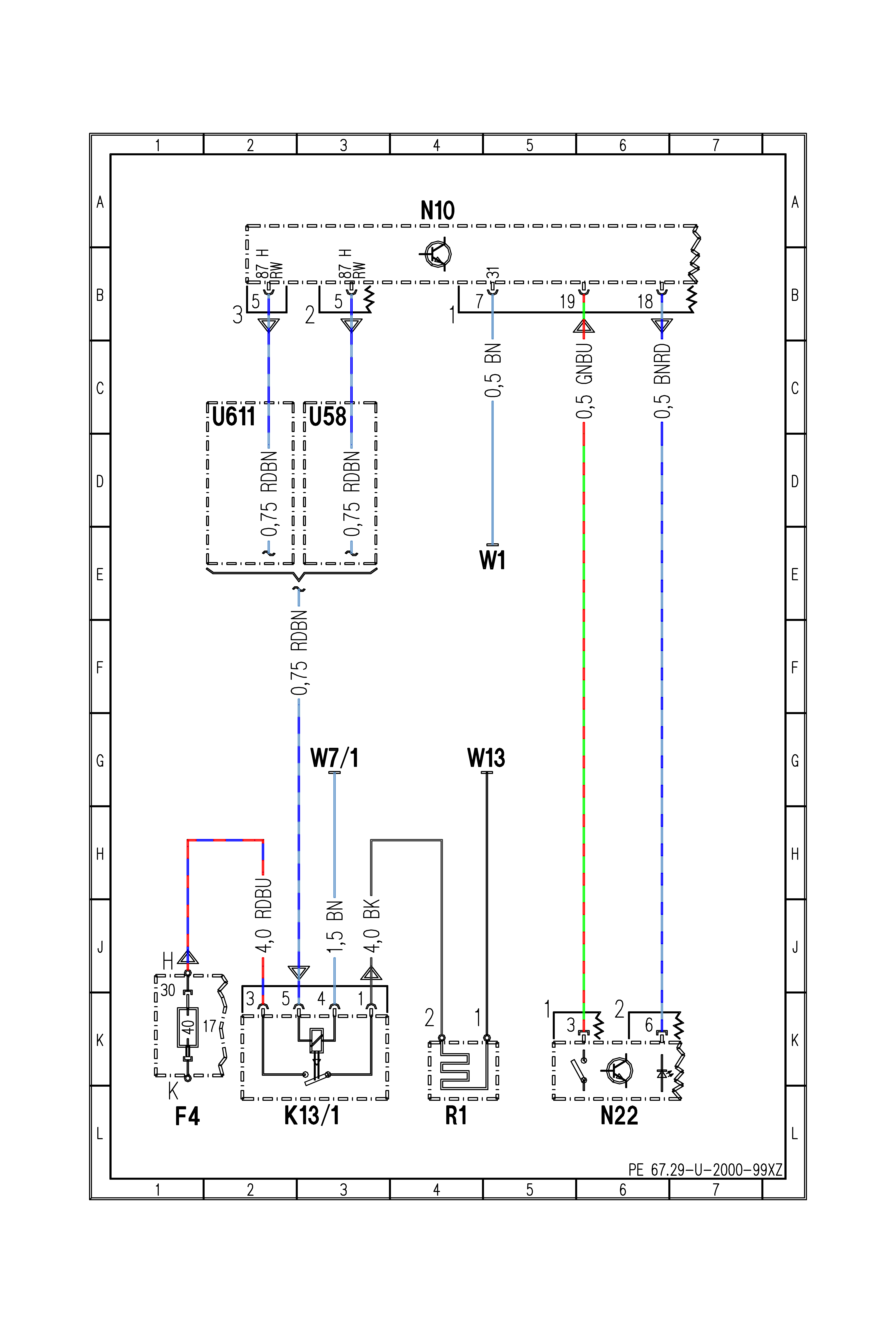
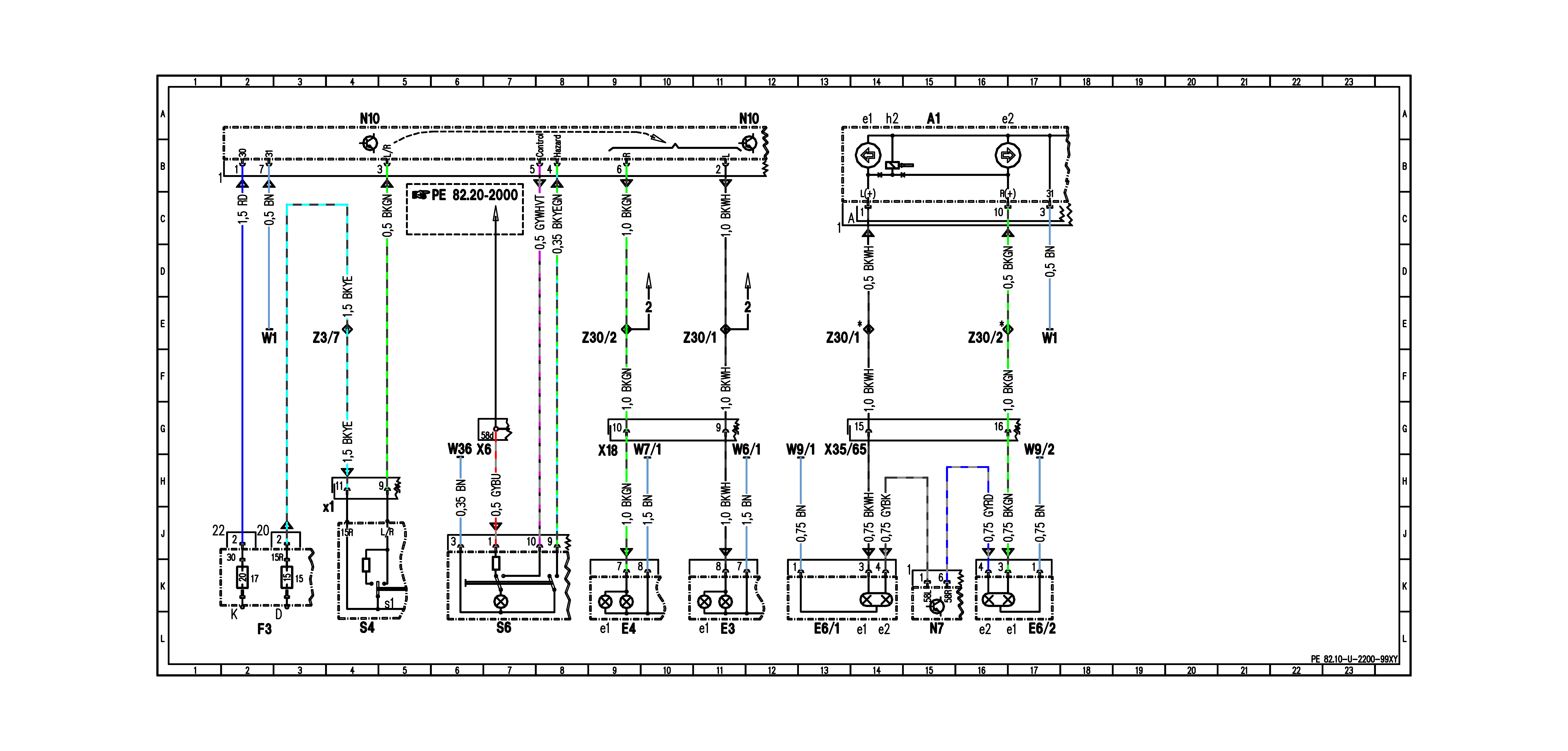
Now, what I have learned is the diagrams are not accurate by any stretch of the imagination, and those Russian diagrams are Chilton Diagrams from the USA.
What I have learned from the N10 wiring is from one year to the next on the same model one(and series-early-mid-late) make no difference. You can be looking at a 97, and the 99 is totally different.
My best suggestion is just wait for someone here to photograph their N10 of the same year, and same model.
You can find the diagrams from this site, but you have to take several steps to view the diagrams, and they cannot work with a tablet or mobile phone as you need to save, download, and upload-That is what it takes-That is what I do to get the most accurate diagrams not these lame Chilton diagrams...
http://benz.ehost.tj/
A)The link will redirect you-accept it.
B)I do not know how it is done with other browsers, but use FireFox with uBlock Origin add-on.
C) Select WebETM with Star Finder
D) For you I THINK !!! It is
82-Electrical Systems Body
E) Windshield Wiper System
F) When you click on the
82.3-U-2000XZ number you will get this page with this heading at the top showing
Diagram/Legend/Diagnostics/Connector/Star Finder, and the page will say
A plugin is needed to display this content. You will go blue in the face before you find the plug-in. This site has been like this because all they have done is copied the actual Mercedes Service CD's, and the CD is like this too.
G) The simplest work-around.
1)I have found is to look at the HTML elements of the page by right clicking on the center of the page, and selecting
Inspect Element.
2)In the element you want to go about half way down. You will see a line with a line that starts with
Frame name= dwf content on that same line you will see
http:// link, and it will end in
html.
3)You want to copy that link, but the easy way is copy the whole line, so right click on that whole line(it will highlight and select
Copy Outer html)Copy the link on Firefox browser address bar, but do open a new tab, so you do not mess-up the page you are on.
4)Change the
html extension to
dwf extension(A CAD file extension) while you are there delete the quotes and the greater-than symbol(These are the symbols
">) . By changing the extension and deleting the quotes, and everything in front of the
http. Then hitting enter you will be prompted to save the file.
5)Save the file where you want, but organize them in a folder as that is what I do.
6) Go back to the page where you exposed the html elements, and close the elements. A tool-bar will be below the actual web page. If you follow the tool-bar to the far right will be an X, hover the mouse over it, and it will say
Close Developer Tools. Click on the X to close it.
7) Now lets convert this
dwf file to something you can use!! :smile
8) Go here to upload the
dwf file to convert it to
PDF:
https://www.coolutils.com/online/DWF-to-PDF#
One-click on
+Select Files it will prompt you to look in your computer for this file. Select
From Local Computer
Two-Blue bar will move from left to right. Meaning file was uploaded.
Three- On step three will say Get converted file select
Download Converted File
Four - their you have your readable schematic diagram
9) Yes that was a pain, but life is just not that easy. it is not easy for me, but I have the GRRRRRit to punch through it is who I am. I have been doing it like this for years.... You must do this if you want to look at the connector diagram too...
10) Lets get back WebETM.
Legend will help with the ID of the parts on the schematic. The Diagnostics will help with the diagnostic test procedures, but under the column
Conn./Plug/Pin that will show the pin-out. The most significant integer is the connector, so the integer changes it means another connector. The "
." separating means the next info is the pin number(the decimal in most cases). The same will exist at near the top of the schematic. The connector designated by a large number outside the connector, and the traces(or wires) pointing to the module will show the pin number.
11)The flat arrows at the connector pointing up/down/up-down means the flow of information.
12)The letters on the traces mean color of the wire, and those numbers on the traces mean diameter of the wire, but do not quote me...
Yes, it takes grit to figure this out, but it works, and I'd take this over having to deal with a non-working car... One has to DIY, this is one of those DIY's for information. Nothing comes easy in this world...
Hope it works out. I did my deed for the day back to some repairs
Martin
PS.. I've cheated and uploaded the N10 diagram, but my goal(here, and anywhere) is for you to find it not for me to do it for you...


