Hi guys!
I finally decided to do the engine wiring harness on my 300 SE 1991 w140, it has a 3,2 Litre motor, so I guess it's the same as the later S320. I'm not sure if all the steps are the same on a 2,8 Litre motor.
It's a job well worth doing, as it costs from about $550-750 to buy a new engine wiring harness online, MB part no: 140 540 10 32. The job of taking it out and putting it back in was about 2 hours in total, but it's easy and if you decide on just buying a new harness instead of rebuilding yours, you can at least save some bucks there. Rebuilding the harness itself is kind of a daunting task, and at one point I seriously regretted not just having bought a new one, but you'll be happy in the end when you see the results.
There are two DIY instructions out there, on how to rebuild the engine wiring harness / MAF wiring. They were great help for me, so I recommend taking a look, but I found there were some steps that could have been covered better in those manuals. Or well, I like making things idiot-proof")
By ScrapingScrap: http://www.benzworld.org/forums/att...hments/w140-s-class/178460d1211131170-knowlege-base-1992-500se-loom-rebuild.pdf
By V12uberalles: Rewiring the MAF Sensor in a W140 Mercedes Benz
Okay. I would recommend that you tackle this job at a time where you won't need your car for some time, as it will take much longer than you expect it to. I'm guessing you could do this faster than I did it (about 16-17 hours in total), but I wanted to be meticulous
You will need:
About 50-60 meters of silicone based wiring, 0,75 mm^2. Where I bought mine, it only came in 100 m rolls. Set me back about 70 dollars. I bought all black wire, as 20 multicoloured ones would have been more expensive than buying a new harness.
Various tools, T20 torx bits, lots and lots of electrical tape (+self vulcanizing tape).
A digital camera to take loads of pictures of everything you do, so you know how to put it all back together right!
A soldering iron + tin
A good place to work on this for a few evenings in a row.
First off:
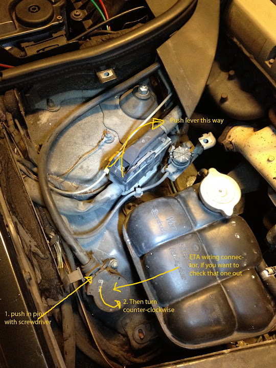
Find the main connector on the passenger side and slide it off, with the lever on top. I also removed the ETA unit to see the condition of the wiring for that.
![Image]()
Remove the weather protection over the wires leading to the middle of the engine bay.
![Image]()
Remove the air intake housing (two 10mm hex-nuts on the sides, then wiggle it off).
Remove the MAF connector.
![Image]()
On inspecting the ETA wiring loom, it was the updated version, with good solid rubber insulation. No need to do anything more than tape it back up and put it back in the car.
![Image]()
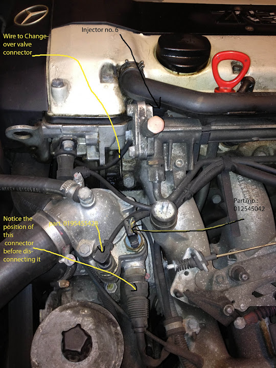
There are three other connectors on the same wiring loom as the MAF connector, their part numbers are:
0195455428 (unknown function)
0125450428 (water temperature sensor? REMEMBER TO TAKE NOTICE OF IT'S POSITION. It can go on both ways.)
126540308 (unkown function, 4 pin sensor, REMEMBER TO TAKE NOTICE OF IT'S POSITION. It can go in any way you want it, so it's important the right sockets go on the right pins, when you install it back in the car).
![Image]()
The wiring harness can be split in two sections:
1.the section going to the above mentioned MAF sensor and other various sensors.
2. the section that contains the injector connectors and the changeover valve connector (I think.. maybe it's the camshaft position sensor?).
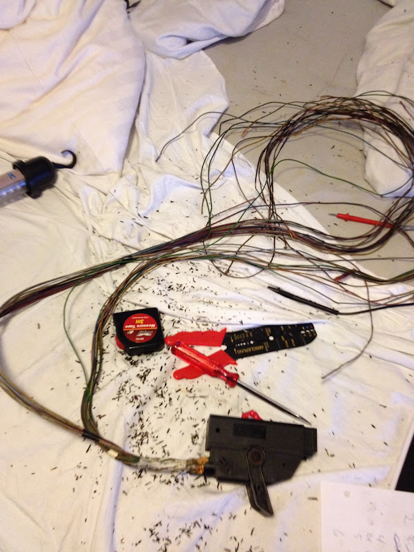
There are a lot of plastic straps that hold the wiring in place, just remove those, buy some new ones in your local hardware store.
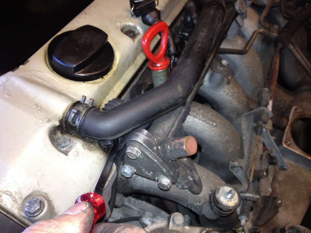
The Changeover valve connector is behind the plastic cover on the front of the engine, with the star on it. It's simple to remove the cover, just push in the plastic pins on the sides.
![Image]()
With that removed you'll see the sparkplug wires and a connector on top of the (camshaft?). Disconnect that connector.
![Image]()
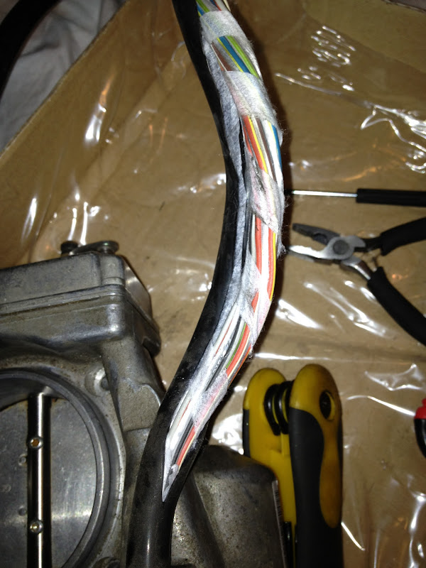
Mine had obviously had some sort of an accident and someone had tried to fix it, without much luck. It was also shorting, and I have a sneaky suspicion it is what caused my transmission to be rather harsh between gears. The wiring to the connector, leads behind a plastic cover on the front of the engine, to protect the spark plug leads from the belts underneath. It is held in place by 4 screws, locations shown in the picture.
![Image]()
One of the screws, closest to the sensor, is hard to remove, hidden well inside a hole. I had to use a T20 torx bit to get to it, as it was the only thing that could reach it. With the plastic cover removed you can get the wire out. When I installed the plastic cover back, I could only put 2 of the 4 screws back. The other 2 wouldn't go in
![Image]()
Push on the sides of the injector connectors and pull gently upwards. They can be a bit hard to get off (especially injector 1, closest to the windscreen).
![Image]()
![Image]()
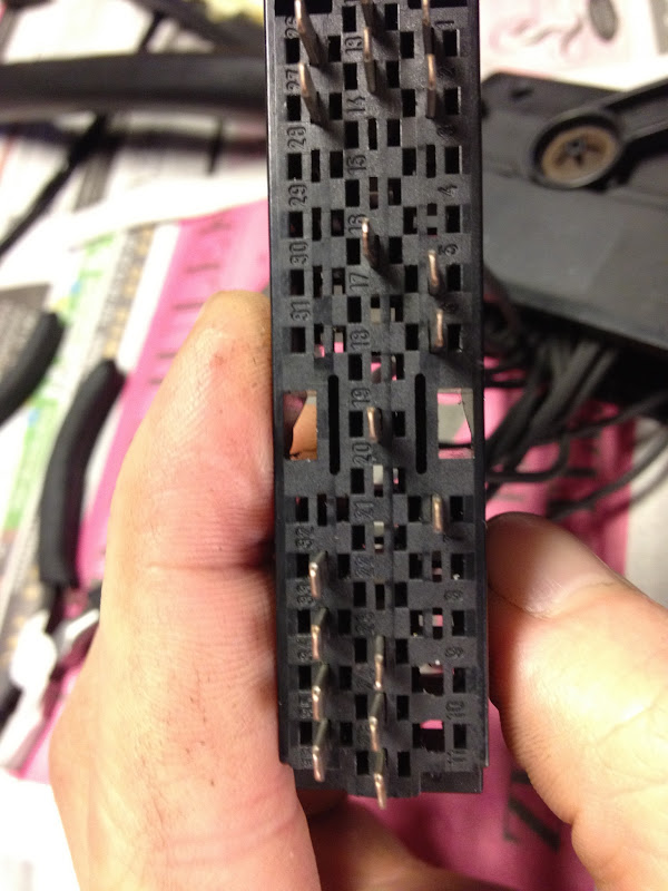
With the wiring harness out, I could start mapping out the connectors on the Main connector and where the pins lead to. It actually took a good while, so I'm supplying you with a map. But for good measure, you should have a voltmeter handy to check your own harness. I found out that the connector for injector 3 was shorting, and the changeover valve connector. My car was thus running on just 5 cylinders
![Image]()
Now to work on dismantling the connectors. The MAF connector is covered in v12uberalles manual. ScrapingScrap has some interesting solutions on the other connectors.
I found that using a hairpin, that I cut down to equal length on both ends, functions very well when you have to get the pins out on the main connector.
![Image]()
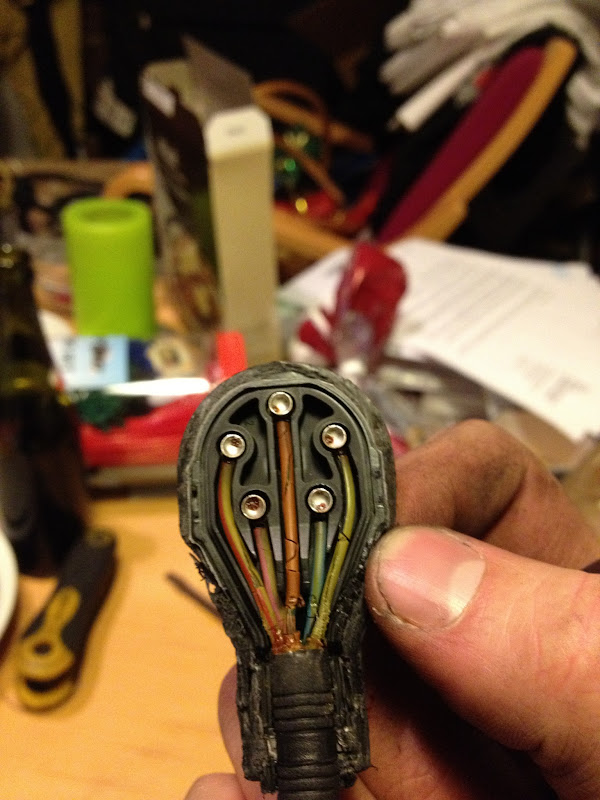
The wiring is held in place with some white goo, when you pull the rubber off on the end. Try to get as much of that off as you can.
![Image]()
![Image]()
Then you will begin to see some yellow hard foamy plastic. That needs to get out as well, but it's a pain in the a***. Get a sharp knife and just cut into the black plastic portion of the main connector. You'll be able to glue it back together nicely later with superglue
![Image]()
![Image]()
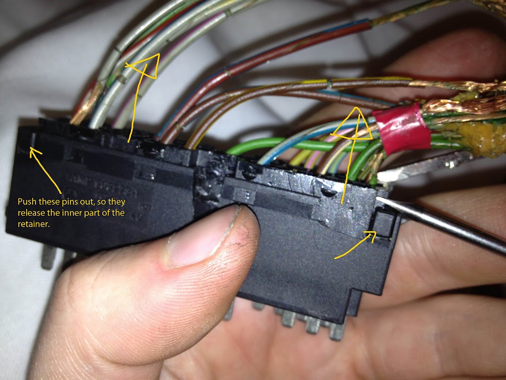
Remove the one screw holding the plastic retainer inside the main connector. Gently pry the retainer out, while pushing the wiring in. It's fiddly.
![Image]()
The retainer is comprised of 3 parts. One outer part, and two inner.
![Image]()
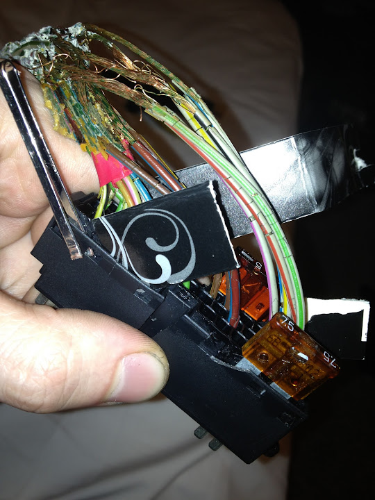
Push something over the little plastic nipplets preventing the inner retainer to be released. I found that old auto fuses were perfect, but also you can just slip a piece of hard paper over each niplet.
![Image]()
![Image]()
![Image]()
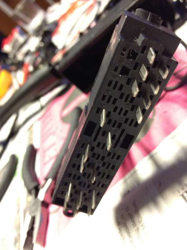
Push the hairpin in on each of the sides of each connector pin on the main connector, then pull on the wire. Do this with each pin.
![Image]()
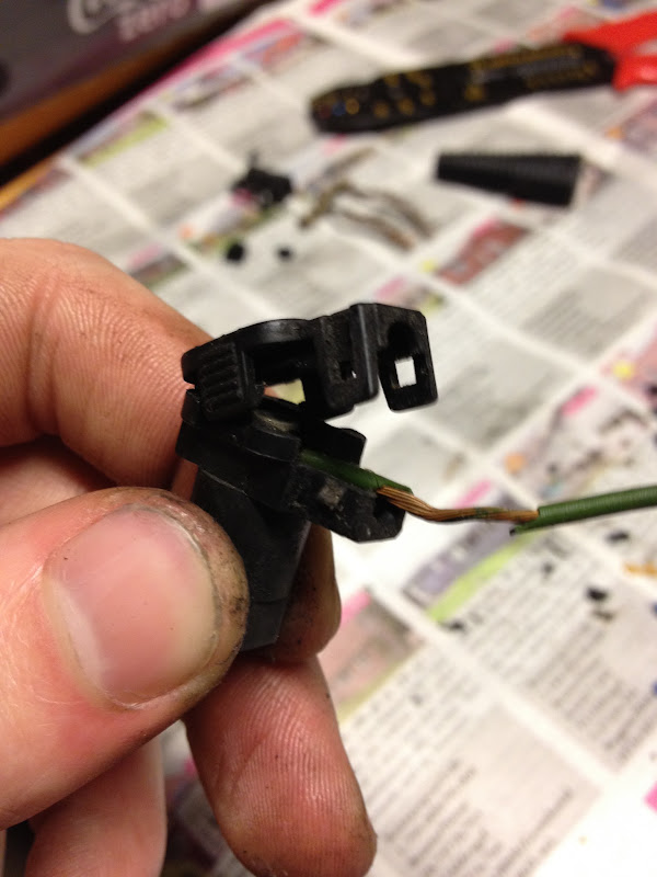
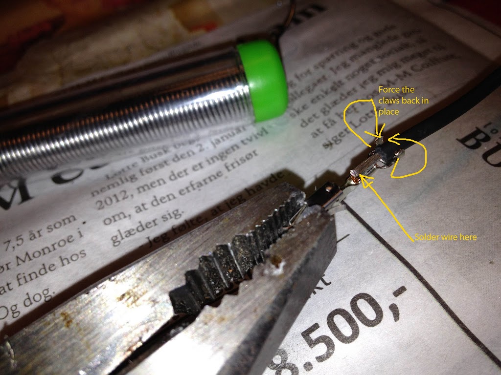
Pry the wires off each pin. You'll solder the new wires back on the pins, but be careful not to damage the "claws" at the back of the pins, as those are useful holding the new wires in place.
This is a picture of the injector sockets, but they are pretty much the same as the pins on the main connector.
![Image]()
![Image]()
Part 2: Removing the injector connector sockets, rebuilding the connectors and putting all the wiring back together.
==> Next post
I finally decided to do the engine wiring harness on my 300 SE 1991 w140, it has a 3,2 Litre motor, so I guess it's the same as the later S320. I'm not sure if all the steps are the same on a 2,8 Litre motor.
It's a job well worth doing, as it costs from about $550-750 to buy a new engine wiring harness online, MB part no: 140 540 10 32. The job of taking it out and putting it back in was about 2 hours in total, but it's easy and if you decide on just buying a new harness instead of rebuilding yours, you can at least save some bucks there. Rebuilding the harness itself is kind of a daunting task, and at one point I seriously regretted not just having bought a new one, but you'll be happy in the end when you see the results.
There are two DIY instructions out there, on how to rebuild the engine wiring harness / MAF wiring. They were great help for me, so I recommend taking a look, but I found there were some steps that could have been covered better in those manuals. Or well, I like making things idiot-proof
By ScrapingScrap: http://www.benzworld.org/forums/att...hments/w140-s-class/178460d1211131170-knowlege-base-1992-500se-loom-rebuild.pdf
By V12uberalles: Rewiring the MAF Sensor in a W140 Mercedes Benz
Okay. I would recommend that you tackle this job at a time where you won't need your car for some time, as it will take much longer than you expect it to. I'm guessing you could do this faster than I did it (about 16-17 hours in total), but I wanted to be meticulous
You will need:
About 50-60 meters of silicone based wiring, 0,75 mm^2. Where I bought mine, it only came in 100 m rolls. Set me back about 70 dollars. I bought all black wire, as 20 multicoloured ones would have been more expensive than buying a new harness.
Various tools, T20 torx bits, lots and lots of electrical tape (+self vulcanizing tape).
A digital camera to take loads of pictures of everything you do, so you know how to put it all back together right!
A soldering iron + tin
A good place to work on this for a few evenings in a row.
First off:
Find the main connector on the passenger side and slide it off, with the lever on top. I also removed the ETA unit to see the condition of the wiring for that.
Remove the weather protection over the wires leading to the middle of the engine bay.

Remove the air intake housing (two 10mm hex-nuts on the sides, then wiggle it off).
Remove the MAF connector.

On inspecting the ETA wiring loom, it was the updated version, with good solid rubber insulation. No need to do anything more than tape it back up and put it back in the car.
There are three other connectors on the same wiring loom as the MAF connector, their part numbers are:
0195455428 (unknown function)
0125450428 (water temperature sensor? REMEMBER TO TAKE NOTICE OF IT'S POSITION. It can go on both ways.)
126540308 (unkown function, 4 pin sensor, REMEMBER TO TAKE NOTICE OF IT'S POSITION. It can go in any way you want it, so it's important the right sockets go on the right pins, when you install it back in the car).
The wiring harness can be split in two sections:
1.the section going to the above mentioned MAF sensor and other various sensors.
2. the section that contains the injector connectors and the changeover valve connector (I think.. maybe it's the camshaft position sensor?).
There are a lot of plastic straps that hold the wiring in place, just remove those, buy some new ones in your local hardware store.
The Changeover valve connector is behind the plastic cover on the front of the engine, with the star on it. It's simple to remove the cover, just push in the plastic pins on the sides.

With that removed you'll see the sparkplug wires and a connector on top of the (camshaft?). Disconnect that connector.

Mine had obviously had some sort of an accident and someone had tried to fix it, without much luck. It was also shorting, and I have a sneaky suspicion it is what caused my transmission to be rather harsh between gears. The wiring to the connector, leads behind a plastic cover on the front of the engine, to protect the spark plug leads from the belts underneath. It is held in place by 4 screws, locations shown in the picture.

One of the screws, closest to the sensor, is hard to remove, hidden well inside a hole. I had to use a T20 torx bit to get to it, as it was the only thing that could reach it. With the plastic cover removed you can get the wire out. When I installed the plastic cover back, I could only put 2 of the 4 screws back. The other 2 wouldn't go in

Push on the sides of the injector connectors and pull gently upwards. They can be a bit hard to get off (especially injector 1, closest to the windscreen).

With the wiring harness out, I could start mapping out the connectors on the Main connector and where the pins lead to. It actually took a good while, so I'm supplying you with a map. But for good measure, you should have a voltmeter handy to check your own harness. I found out that the connector for injector 3 was shorting, and the changeover valve connector. My car was thus running on just 5 cylinders

Now to work on dismantling the connectors. The MAF connector is covered in v12uberalles manual. ScrapingScrap has some interesting solutions on the other connectors.
I found that using a hairpin, that I cut down to equal length on both ends, functions very well when you have to get the pins out on the main connector.

The wiring is held in place with some white goo, when you pull the rubber off on the end. Try to get as much of that off as you can.


Then you will begin to see some yellow hard foamy plastic. That needs to get out as well, but it's a pain in the a***. Get a sharp knife and just cut into the black plastic portion of the main connector. You'll be able to glue it back together nicely later with superglue


Remove the one screw holding the plastic retainer inside the main connector. Gently pry the retainer out, while pushing the wiring in. It's fiddly.

The retainer is comprised of 3 parts. One outer part, and two inner.

Push something over the little plastic nipplets preventing the inner retainer to be released. I found that old auto fuses were perfect, but also you can just slip a piece of hard paper over each niplet.

Push the hairpin in on each of the sides of each connector pin on the main connector, then pull on the wire. Do this with each pin.

Pry the wires off each pin. You'll solder the new wires back on the pins, but be careful not to damage the "claws" at the back of the pins, as those are useful holding the new wires in place.
This is a picture of the injector sockets, but they are pretty much the same as the pins on the main connector.

Part 2: Removing the injector connector sockets, rebuilding the connectors and putting all the wiring back together.
==> Next post