Mercedes-Benz Forum banner

O2 sensor wiring

36K views 23 replies 3 participants last post by  Saffree  
#1 ·
So, investigating further my lambda readings on one bank of the M120

Two weeks ago, after gutting the passenger side cat, my lambda went to 50%, and varied a bit, as it should.

Today, noticing a rich exhaust smell, I checked it again. Steady at 70%. No voltage fluctuation. Up on the jackstands it goes again.

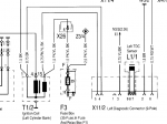
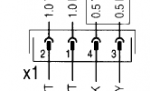
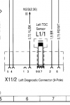
Ran a wire from under the hood to the connector for the passenger side 02 sensor. I'm showing continuity between all 4 pins on the 02 harness socket and pin 3 of the X11 connector on the fenderwell. This tells me I have a short somewhere in the harness.

As I don't have wiring diagrams, I'm not sure where to begin. I think I'll replace section of the harness. But with a 4 wire harness, that represents a heated O2 sensor. My new ones are not heated; nor were the old ones.

Where do I start tracing the wires? And can anyone assist me with a wiring diagram? I want to know the interconnections between the X11 diagnostic port, the LH compter harness and the O2 sensor.

Regards
 
#2 ·
Ok, I found a wiring diagram for a 1992. On pg 3, it shows the harness from the O2 sensor goes directly to the X11 diagnostic port (the small one on the side of the fenders).

According to this diagram, the ratio test should be done on connectors 3 and 4. Pin 4 is designated as the O2 sensor output.

However, on K6JRF's page, he says it's pins 2 and 3. Pin 3 is designated as the O2 sensor output.

The only good news is that the 4-element wire from the X11 runs straight down to the O2 sensor. So it should be simple to replace it and see if I get an improvement.

Now, I just need to figure out if the wiring diagram is correct.

Cheers
 

Attachments

#3 · (Edited)
Now, I just need to figure out if the wiring diagram is correct.
I am a little confused.

Your car has no cats. The exhaust will smell rich, regardless of what the O2 sensor does.

Now, wiring for the O2-sensors.
All cars made in the last 30 years or so will have heated O2-sensor.
On the classic 3-wire design, there will be a signal wire and two wires the do the heating (one of which is switched 12V, the other ground).

Notice that the signal (0.1-0.9 V generated from the sensor) is referenced against the exhaust(engine) ground -- the metal enclosure of the sensor is the ground. This is for the 3-wire design, which is the weakest link, as the corrosion in the exhaust causes all sort of problems.

This is why the 4-wire design has a separate ground wire for the signal and this is exactly what the electrical diagram has. 1 and 3 are grounds, 4 is signal, and 2 should be the heater +.

Where exactly did you measure zero Ohm to conclude you have a short in the circuit?
The sensor heater should have low resistance and with a cheap VOM, you may not be able to tell if you are measuring the resistance of the wire or the element.

Good luck,
Steve
 
#4 ·
Steve,

See if this makes sense, because it doesn't to me.

I get it about the 4 wire. I just back out from under the car. It does have 4 wires on the sensor.

To test it, I had my mechanic under the car. Unplugged the harness from the sensor. Put my meter (it's a $300 Fluke) negative into pin 3 on the X11. Ran a wire from on top of the engine outside the car to the harness on the exhaust. One pin at a time my mechanic put the end of the wire into the 4 sockets of the harness.

From 3 of the 4 sockets I get continuity (that is, between the lower part of the harness that plugs into the sensor and pin 3 of the X11). Some of that may be from the LH computer itself. Tomorrow I'm going to remove the LH computers and try this again.

Now, I was just testing running voltage. I totally get that an O2 sensor should not put out more than 0.9v. Mine are new Bosch from Pelican parts. Not even a year old.

When measuring the voltage from pin 2 to pin 3, one bank (the one that shows 50% lambda) reads voltage that fluctuates between 6.6 and 7.7 volts. And I can run the volt scale up and down and still get the same reading. It's fluctuating, which tells me it reading the output of the sensor.

Now on the other bank, the lambda reading is a constant 70% between 2 and 3. And the voltage reads 10.6 volts. Revving the engine makes little change.

The voltage on pins 4 for both X11s read battery voltage.

So, where is the voltage multiplication coming from? My thought is that if there is a short on the bank that shows a constant reading, the wire running to pin 3 is most likely picking voltage from the +12v pulsed wire.

At this point, I'm not sure what other sense to make of it.

It's dark here now, so can't do any more testing tonight.

Tomorrow, I pull the LH computers and check continuity again.

Cheers
 
#5 ·
Steve

Another one on this. Snapshot from the wiring diagram attached.

As I read this, on the X11 (X1 on the diagram), 1 & 2 would be the pulsed 12v to the heater (not grounds). 3 & 4 would be the output of the sensor. 3 is also shown grounded to the exhaust.

It also makes sense that 3 & 4 should be the sensor output, as the diagram shows a shielded run to the LH computer. That makes sense for voltage in the range of 0.1 to 0.9v.

Cheers
 

Attachments

#6 · (Edited)
Tomorrow, I pull the LH computers and check continuity again.
Agreed. With the O2-sensor disconnected and LH computer out, you should test the wires from pin 4 (X11) to pin 14 and from pin 3 (X11) to pin 15.

EDIT: white wires are the heater, black (#3) is signal and grey (#4) is ground. I had it wrong before, I am sorry for the confusion.

Image


Then, you should repeat pin 14/15 from the LH to the female connector in the transmission tunnel.
Same for pins 3/4 to the female connector in the transmission tunnel.

If there is a broken/shorted wire you'd know immediately.

What you are doing know is you're measuring something (black magic) coming from the LH -- which is why across pins 2 and 3 of the X11 port you are not supposed to use a voltmeter, but a scope to show %.

I am afraid you may find out that the wiring is fine but the ECU is likely damaged....

Steve
 
#8 ·
As to not using a meter but only a scope...

Everywhere I've seen [e.g: URL="https://www.youtube.com/watch?v=5syKYwfEyCo"]https://www.youtube.com/watch?v=5syKYwfEyCo[/URL] and read [e.g K6JRF], a meter set to the duty cycle is used.

My pocket scope (really cool Arduino unit) mysteriously walked away while I was travelling this summer.

Cheers
 
#11 · (Edited)
Just a thought: could the LH system for the left bank be running in 'closed' mode, not 'open mode'.
Let's define left and right. I am old school.
As I stand in front of the car, and look at the engine:

On my left is bank 1 (passenger side)
On my right is bank 2 (driver side)

Bank 1 = cylinders 1 through 6
Bank 2 = cylinders 7 through 12

Agreed?

Now let's define closed- and open-loop.

Closed-loop means the engine has reached operating temperature, and the O2-sensors provide feedback to the ECU to adjust fueling.

Open-loop means the engine is typically cold, and the O2-sensors do NOT provide feedback to the ECU to adjust fueling, therefore the ECU runs off of the default map.

Sleep on it, test the wiring tomorrow, swap (if needed) O2-sensors left to right, swap (if needed) LH ECUs left to right, and we will find the answer.

Good luck,
Steve
 
#12 ·
Success!

Steve: Correct, looking from in front of the car, left and right cylinders are you describe. And yes, open and closed loop as you described.

So, pulled out both LH computers. Got under the car and cleaned the chassis mounter O2 sensor connectors. Measured for continuity between the connectors in the drive tunnel and the sockets for the computers.

Not surprisingly, one of the pins (of course it had to be the O2 hot pin) was a bit tarnished (not quite corroded). Cleaned it with de-ox solution. Continuity was good.

Just for fun, I swapped the O2 sensors. They were easy because I had used Never-Sieze when installing them a few months ago.

Reinstalled the LH computers.

Car fired up and was definitely smoother after it warmed up. Monitoring the lambda ration on both X11s I could see where they started at appx 70%. Once the car warmed a bit, the LHs started to adjust.

Both settled around 50%, but more importantly, I could see the adjustements as the ratio measurements fluctuated.

Just for fun, once the car warmed up, I disconnected each sensor, one at a time. I could watch the lambda ratio go right back to 70%, even with a warm engine.

And logically, the dirt that was on the connectors was where you would first expect it: in the trans tunnel. The O-rings on the connectors were in good shape, but just to make sure I applied silicon grease to them. I live in a VERY dusty environment.

I can't wait to drive this thing tonight and see what it feels like. The exhaust definitely smells different, and, and parked, the engine seems to rev smoother.

Cheers
 
#13 · (Edited)
Just for fun, I swapped the O2 sensors.
I must ask (and should have asked earlier). Are the locations of the x11 diagnostic ports in correspondence with the other engine parts?

By that, I mean, the EZL and ETAs for example are reversed:

View attachment 2282065


M16/3 is what MB calls left ETA and it is on the drivers side.
M16/4 is what MB calls right ETA and it is on the passenger side.

Is this how the x11's are?

Steve

PS And to confirm -- the measurements were taken at pins 3 and 4, right?
 
#14 ·
Steve,

The X11s are reversed as well. So, if I'm standing in front of the engine, the X11 on the left side is reading the O2 sensor on the right exhaust pipe. It is the diagnostic port for the fuel and ignition components on the left bank of the engine.

Took me a while working on the car to become familiar with that layout.

As to the X11 itself, mine do not have any electrical connector in the #1 port. Just ports (pins?) 2 through 5. 5 is definitely battery voltage. As we have found out, 3&4 are for the O2 sensor. 2 & 1 are supposed to be for the pulsed O2 heaters.

Cheers
 
#15 ·
Just a quick update

The car is completely transformed, now that both banks are running in closed loop mode. It's what I have been expecting this V12 to run like.

My friend at the coffee shop where I get internet told me he didnt even hear the car coming in today. The exhaust is so much quieter. And the engine has smoothed out quite a bit in terms of vibration.

I"m hoping this weekend to take it on the open road upcountry to see what it can do.

It's amazing what 1 dirty pin on the oxygen sensor can do to the vehicle.

The scary part is that no dash lights are thrown when this condition occurs. I guess if you have an Star system you'd be able to find it, but if you don't, there is no way to check this unless you measure the cold and warm lambda readings.

Cheers
 
#17 ·
For clarity on diagnosing the lambda measurements, the X11 connector I was talking about is referenced as X11/2 and X11/3 (9 position analog diagnostic ports) positioned on the left and right fenders (in front of the EZL computers).

As you can see from the diagram, the lambda duty cycle measurements ARE taken from pin 3 (lambda signal; + lead) and pin 2 (ground).

Previously in the thread, Steve and I were discussing the connections to the X1 connector (the one mounted on the transmission tunnel, that the O2 sensor plugs into). On that connector, the O2 signals are indeed on pins 3 and 4 (3 being the ground and 4 being the O2 signal). But is is very difficult to take diagnostic readings from that one, unless you like pulling up the carpet.

I hope this clarifies things. The article by K6JRF's page on his S500 is correct for our S600s.

Cheers
 

Attachments

#18 · (Edited)
For clarity on diagnosing the lambda measurements, the X11 connector I was talking about is referenced as X11/2 and X11/3 (9 position analog diagnostic ports) positioned on the left and right fenders (in front of the EZL computers).
Obviously I haven taken any measurements from those diagnostic ports and you now have me even more confused.

Which one is X11 on the picture. This is my passenger side fender well.


View attachment 2282809


All the time we where discussing it, I thought it was the one with the cap....?
The bottom one with the TDC sensor was deleted as soon as MY 1994 (and Jim's S500 is 1994 IIRC)


Steve

EDIT I have a somewhat unfair advantage to other listers here as I can read and understand other languages, and can use web-resources that are not of use to many here.
According to this diagram and the description here

View attachment 2282833

X11/2 and X11/3 are diagnostic ports with the CAP
 
#19 · (Edited)
The scary part is that no dash lights are thrown when this condition occurs. I guess if you have an Star system you'd be able to find it, but if you don't, there is no way to check this unless you measure the cold and warm lambda readings.
This is strange, does you Check Engine Light ever comes on? I mean it should be lit when you have the ignition ON and then go off.
According to the manual for the 1992/93 CEL should illuminate if there is a problem with the O2-sensors. Certainly true for US-versions of the 600SEL/SEC. California vehicles will also through CEL if there are issues with the smog pump and/or EVAP system


It's amazing what 1 dirty pin on the oxygen sensor can do to the vehicle.
I'd err on the side of caution here. Too early to claim victory. There is another ongoing thread, where the OP had poor running and could not revv the engine, loss of power. Blew fuses. He claimed that hi disconnected the bad O2 sensor and the car runs superbly. 1998 S600. IMHO, also questionable.

I do not know anything for the ME-cars, but the LH-cars will actually run better in open loop. Here is the relationship between some parameters of the burning and lambda.

Image


Based on it, ICE will run better at around 13:1. 14.7:1 is a compromise for the sake of emissions. If you have no cats, unplug both sensors and take the beast on the open road. CEL will be ON (and I wouldn't worry about since there is nothing to melt in the exhaust pipe) but you'll be amazed....

Steve
 
#20 ·
Steve,

From your picture: it's the top one with the cover. Same as mine.

According to the electrical diagram I have, it's X11/2 (on the left fender well). I'll attach the extract from the diagram again.

First attachment: legend from the wiring diagram. Show the location on the electrical schematic for X11/2 and X11/3.

Moving to 5M on the page where the left hand X11/2 connector is found. (2nd attachment). You'll see that it includes the TDC connector. Pin 2 is ground. Pin 3 goes to N/2 pin 36 on the second connector. Also notice that pin 1 has no connector. Pin 6 is battery voltage.

3rd attachment. Pin out diagram from ALLDiYDate. Pin 36 is the on-off ratio connector.

Hence, my conclusion that pins 2 and 3 are used for the on-off ratio test for the O2 sensor.

As to the language issue, I'll concede you do have an advantage. I fluent in American and Swahili. And not too much in the way of Mercedes documentation in Swahili. :laugh

I'll address your next post in my next post.

Cheers
 

Attachments

#21 ·
Steve,

Now to your post about the O2 sensors.

I was wondering about disconnecting both sensors and running the car. Unfortunately, I'm off tomorrow for the states for 2 months, so I won't have a chance to try this until I return. Someone broke into one of my garages in Baltimore and trashed my TVR that I just recovered after being stolen for 23 years, and I need to go deal with that. Then my boat in Seattle is slowly sinking as my prop shaft seal got trashed this fall during a gale on the way to Alaska. So I have to deal with that one as well. But I digress...

I was also wondering about open vs closed loop performance. One difference is that I'm up at about 1.3km altitude here. Air is definitely thinner here. But I guess not that different from the Alps. I always thought that O2 sensors with a closed loop system constituted a performance increase over an open loop system.

Where did you find a reference that the LH systems run better in open loop? I've got all the Bosch FI books and have read a ton on the systems, and haven't come across that one. It would be interesting to know for sure. As I have no cats anymore, I don't really need the sensors if they are going to detract from the performance.

"If you have no cats, unplug both sensors and take the beast on the open road.": Open road? Around here? I wish...

As to the CEL: I don't have one. I guess my car was upgraded to the 'Exhaust Overheat" warning light.

Cheers
 
#22 · (Edited)
From your picture: it's the top one with the cover. Same as mine.

I am having a bad day. What I posted earlier with the question as to which X11 is a complete nonsense. The lower connector is for the ETA, of course, what was I thinking....

Sorry about the confusion. I guess the open question remaining is -- when did MB delete the diagnostic ports? 1994 or 1995?

Steve
 
#23 · (Edited)
I was also wondering about open vs closed loop performance. One difference is that I'm up at about 1.3km altitude here. Air is definitely thinner here. But I guess not that different from the Alps. I always thought that O2 sensors with a closed loop system constituted a performance increase over an open loop system.
This primarily is the job of the MAF (and the barometric sensor, if fitted) to adjust the fueling.
O2-sensor and altitude.....hmmm...there is a connection but not straightforward. I will have to think about it

Where did you find a reference that the LH systems run better in open loop? I've got all the Bosch FI books and have read a ton on the systems, and haven't come across that one. It would be interesting to know for sure.
O2-sensor feedback is ignored by most early FI systems (not just Bosch LH) past ca. 2500 rpm and this is the range most engines are at peak torque and approaching max. power output.

O2-sensor feedback provides for better fuel economy and less pollution. For better performance air:fuel ratio of 12-13:1 is ideal.

Hot-rod literature abound of examples:

Air-Fuel Ratio Meter Tuning - Hot Rod Network

Also, recall that is impossible to tune a carb to 14.7:1.

ME-SFI automatically (re)adapt itself every a couple of starts and I am not sure what will happen if you just unplug the two upstream O2-sensors.

Open road? Around here? I wish...
Didn't you say earlier that the Chinese had built a new highway?


As to the CEL: I don't have one. I guess my car was upgraded to the 'Exhaust Overheat" warning light.
Being a Japanese import, I understand the temp. sensor in the catalytic converter but I was under the impression that there is a CEL too.
I am sorry If I have it wrong.

Steve