By turning the pump I meant swivel the pump, like you did.
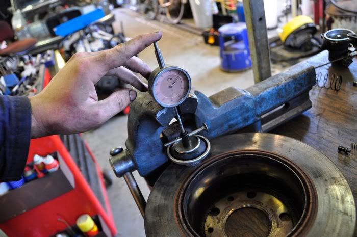
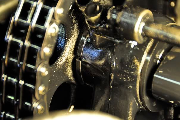
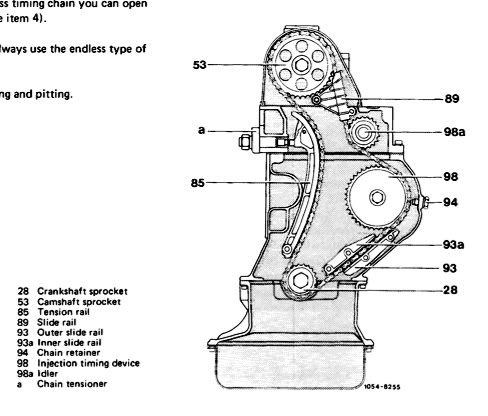
You can check the timing chain stretch by putting the camshaft exactly on its mark:
and than reading the position of the crankshaft
In this case about six degrees late. More than six degrees is not good and the timing chain should be replaced.
Jumping a teeth is not very likely, unless you turned the engine in the wrong way or used the camshaft bolt to turn the engine. Timing chain stretch is was normally delays injection timing and valve timing.
The overflow method.
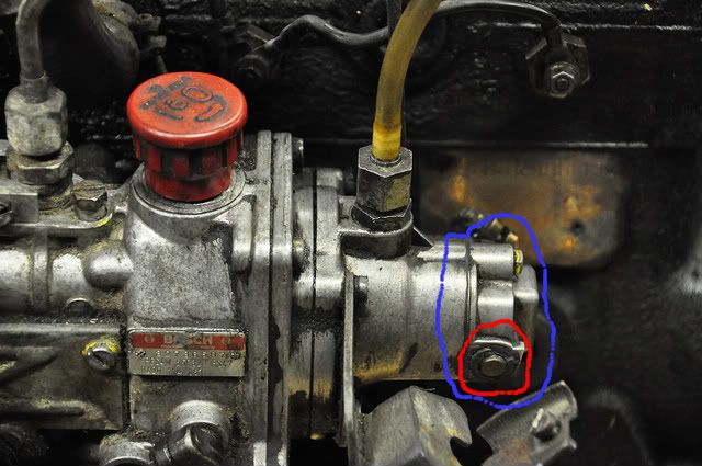
You start by cleaning your diesel pump, use brake cleaner, toothbrush and such like so that there is no dirt on the outside. Remove the securing bolt with the two half moons that is inbetween the pipe connections.
Move engine to about 30 degrees BTDC in the compression stroke of cylinder 1.
Remove the injector line from cylinder one. Here you can see the pipe connections without the injector lines. You need only to remove the first line at this stage. It is a slightly more modern MRSF pump, but the principle is the same. Remove the securing bolt with the two half moons that is inbetween the pipe connections.
Now unscrew the pipe connection and carefully lift it out, now you can see this:
Take a pair of pliers (clean it first thoroughly with brake cleaner or something similar) and carefully remove the spring.
Now you can see this, the delivery valve in the delivery valve holder and a copper seal ring.
Use the pliers to remove the delivery valve
And store both spring and delivery valve in a safe and clean spot:
Now you see this, the delivery valve holder and the copper ring.
Make sure it is somewhat in the middle, screw back the pipe connection and torque to about 30-35 Nm. Screw on the spout.
Start and keep pumping the hand pump and watch the spout. When it drips about 1 drip a second, it is the start of delivery. If it is flowing, the engine has to turn further. If it doesn't drip, start of delivery has passed.
Here is a youtube movie, not entirely perfect, but you get the idea of the dripping. I was hand pumping and filming at the same time, I swivelled the pump some more to get the correct dripping.
YouTube - Timing MRSF diesel pump on a Mercedes-Benz OM616 engine
Normally the diesel will flow at 30 degrees BTDC. Now turn the engine a degree at the time until diesel starts to drip at 1 drop a second. Now read the position of the engine on the harmonic balancer. If adjustment is necessary, unscrew the three bolts, the bolt at the back of the pump and the hard injector lines. Swivel the pump to adjust, towards the engine advances the start of delivery; from the engine is a later begin of delivery.
When you start pumping the handpump, fasten a bolt of the diesel pump, otherwise timing might be affected. If correct fasten the other two.
There should not be pressure on the hard injector lines when you screw them back on. Bent them by hand and carefully.
Now the spout can be removed. Unscrew the pipe connection. Renew the copper washer (get one at the MB dealer, do not use a generic copper washer) and you might want to renew the rubber O ring around the pipe connection. Put back the delivery valve and spring. Screw the pipe connection into place. Now you need to torque it, that is essential. First torque to 30 Nm, than loosen it. Torque it again to 30 Nm and loosen it. Now finally torque it to 35 Nm. Put back the bolt with the two half moons.


") .
.