

Probably a pretty odd first post, but have used this forum to help sort mates merc's and feel I better stick something back to the community. Hopefully save a few of you a grand!
To start, this is the pump assembly from a W200 S55 amg, after a heavy winter the thing started blowing its fuse regularly, google pointed me here for the suspected fuse and the general consensus that water ingress/condensation was at fault, and a new unit required as it is coded to the alarm.
Now im a mechanic, but also have a degree in electronic engineering, so 9/10 times i manage to repair units like this/ecu's/EPS set-ups and so on and retain the original coding. Thus avoiding the main stealer's. Given this pump was essentially a lost cause, further investigation was warranted.
Electronically the pump checked out, but current draw was excessive, i suspected a stalled motor, either corroded or jammed.
Here is the unit with the main half's pried apart and the pump separate from the valve body and control circuits
![Image]()
at this point you ought to apply 12v through a 5A FUSED!! supply (like a PowerProbe) to the motor directly, then if the motor doesn't stall, block either the outlet or inlet and see if it stalls. (it should never stall). if it stalls your onto a winner, the pump or motor are at fault.
note the white marking to ensure the orientation is correct on disassembly, remove the securing torx bolts but hold the pump together with a spare finger!
slowly remove the metal ring that sat under the torx bolts
slowly remove the top carbon/graphite cover
now the next bit is very tricky, you need to remove the centre part, without dislodging the little blades so they stay in the correct grooves, to do this you need to hold the centre graphite ring, and the part wit the slats as one, once removed vertically place against a peace of paper and you can then lean it on the paper till it can be layed down on a flat surface.
Holding: -
![Image]()
once laid down: -
![Image]()
you should now be left with this: -
![Image]()
gently holding the remaining carbon/graphite piece thats attached to the motor, power the motor up again. if the motor still stalls out, you have a motor problem and will be on your own if the motor spins fine then the issue lies with the carbon/graphite pump assembly!
now if you look at the last photo you can clearly see where the pump has "ran" on the surface, its this shiny stuff that's causing the pump to stick, it needs buffed back to be the same as the rest of the surface. this is achieved by (and i cannot stress this enough) VERY!!!!!! gently buffing with 1500grit wet and dry paper, DRY! do this to every shiny part of the pumps internals, be very careful not to accidentally round any sharp edges and be very careful when buffing the individual blades and the contoured edge that makes contact with the centre ring.
once done, reassemble, only nipping all the torx bits give it a wee shoogle to centre it all then final tighten. don't go wild, the pump is made of a light brittle material, you don't want to brake it! and repeat the test with the fused supply, all being well the pump will run like a dream and not stall!
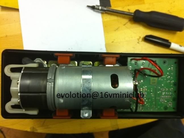
reassemble: -
![Image]()
and refit to the car! .. I hope you marked all those vacuum pipes :thumbsup:
A final note, a few people said to me while i was doing this, "why not squirt in some wd40" simple, this pump is made of a material which is clearly self lubricating, same sorta stuff motor brushes are made off. if you were you introduce a liquid lubricant any deposits would stick to the liquid, before you know it the liquid becomes a paste, to be more precise, a grinding paste
also i wore powder free latex gloves to do this as i feel even the oil from your fingers would hinder the materials lubricating properties!
enjoy
-- to the mods/long term members, feel free to host the pics on a local server if there of use and edit the links, as i may not have my photo-bucket forever
To start, this is the pump assembly from a W200 S55 amg, after a heavy winter the thing started blowing its fuse regularly, google pointed me here for the suspected fuse and the general consensus that water ingress/condensation was at fault, and a new unit required as it is coded to the alarm.
Now im a mechanic, but also have a degree in electronic engineering, so 9/10 times i manage to repair units like this/ecu's/EPS set-ups and so on and retain the original coding. Thus avoiding the main stealer's. Given this pump was essentially a lost cause, further investigation was warranted.
Electronically the pump checked out, but current draw was excessive, i suspected a stalled motor, either corroded or jammed.
Here is the unit with the main half's pried apart and the pump separate from the valve body and control circuits
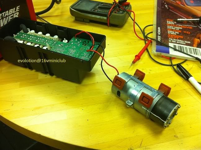
at this point you ought to apply 12v through a 5A FUSED!! supply (like a PowerProbe) to the motor directly, then if the motor doesn't stall, block either the outlet or inlet and see if it stalls. (it should never stall). if it stalls your onto a winner, the pump or motor are at fault.
note the white marking to ensure the orientation is correct on disassembly, remove the securing torx bolts but hold the pump together with a spare finger!
slowly remove the metal ring that sat under the torx bolts
slowly remove the top carbon/graphite cover
now the next bit is very tricky, you need to remove the centre part, without dislodging the little blades so they stay in the correct grooves, to do this you need to hold the centre graphite ring, and the part wit the slats as one, once removed vertically place against a peace of paper and you can then lean it on the paper till it can be layed down on a flat surface.
Holding: -

once laid down: -
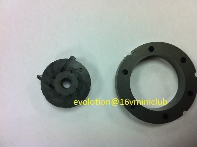
you should now be left with this: -
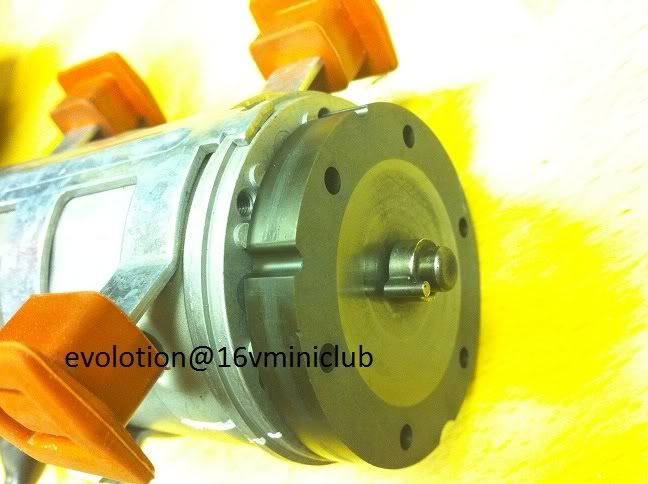
gently holding the remaining carbon/graphite piece thats attached to the motor, power the motor up again. if the motor still stalls out, you have a motor problem and will be on your own
if the motor spins fine then the issue lies with the carbon/graphite pump assembly!now if you look at the last photo you can clearly see where the pump has "ran" on the surface, its this shiny stuff that's causing the pump to stick, it needs buffed back to be the same as the rest of the surface. this is achieved by (and i cannot stress this enough) VERY!!!!!! gently buffing with 1500grit wet and dry paper, DRY! do this to every shiny part of the pumps internals, be very careful not to accidentally round any sharp edges and be very careful when buffing the individual blades and the contoured edge that makes contact with the centre ring.
once done, reassemble, only nipping all the torx bits give it a wee shoogle to centre it all then final tighten. don't go wild, the pump is made of a light brittle material, you don't want to brake it! and repeat the test with the fused supply, all being well the pump will run like a dream and not stall!
reassemble: -
and refit to the car! .. I hope you marked all those vacuum pipes :thumbsup:
A final note, a few people said to me while i was doing this, "why not squirt in some wd40" simple, this pump is made of a material which is clearly self lubricating, same sorta stuff motor brushes are made off. if you were you introduce a liquid lubricant any deposits would stick to the liquid, before you know it the liquid becomes a paste, to be more precise, a grinding paste
also i wore powder free latex gloves to do this as i feel even the oil from your fingers would hinder the materials lubricating properties!
enjoy
-- to the mods/long term members, feel free to host the pics on a local server if there of use and edit the links, as i may not have my photo-bucket forever


