

Ok everyone I finally found some time to put together the pictures and details of the Mercedes Airmatic shock assembly. I did not include the pictures showing the epoxy cracking issue around the top section of the shock. I know there is some older post showing the problem and solutions for that repair. I think it would be a great idea for someone to find that post and copy it into this thread. That way we can try to keep as many air suspension posts in this thread as possible. This will allow everyone to see questions and solutions for repairing their air suspension without searching all over the forums. We are also finalizing remanufacturing the ABC shocks at the time of this publication. Once that process is complete, I will do the same thing and post pictures showing everyone the failure points to look for when diagnosing the ABC suspension systems. I will also post pictures and details on our coil spring replacement system due to launch in another couple months. If anyone has any questions, please feel free to e-mail me directly at adam@arnottinc.com.
Thanks everyone!
Adam
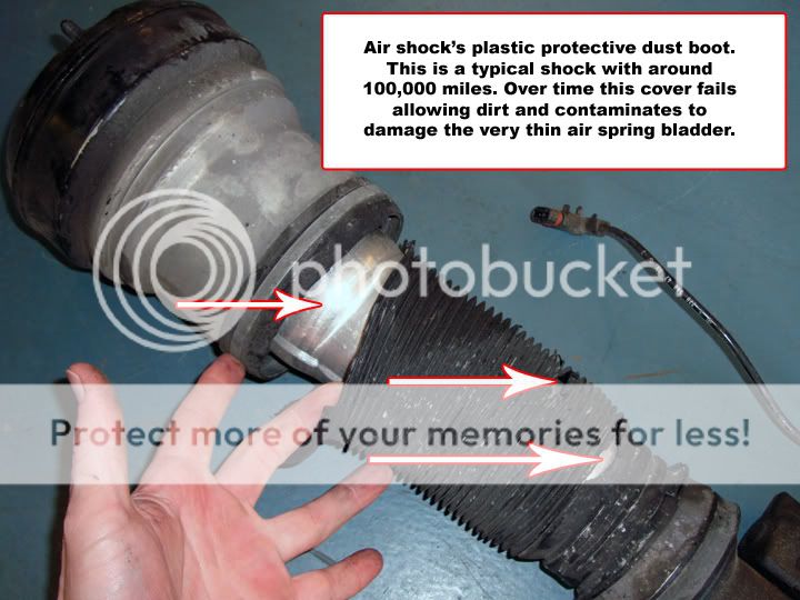
1. The first picture shows you an example of a worn lower dust cover on an Airmatic shock. Once you start to see this on your shock, the end is near.
2. The next image shows a typical worn upper mount removed from a shock with around 80,000 to 100,000 miles. A worn mount will contribute to many unwanted problems with your suspension.

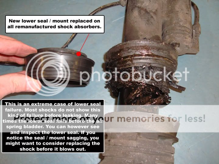
3. One common failure of an Airmatic shock is the lower piston seal. The lower seal is designed to flex and absorb vibrations from the road. Oil, dirt, and heat degrade the rubber over time causing the lower seal to fail. This picture shows an extreme failure of the lower seal. It’s not a bad idea to lift your vehicle and inspect this seal around every 20K miles or so.
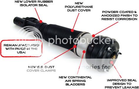
4. Now we are moving into the air spring side of the assembly. This is the part of the shock you cannot see because it’s located behind the silver aluminum section of the shock. In order to remanufacture the shock we have to machine off the can to replace the air spring. The can is then powder coated and reassembled back onto the shock during the reassembly process later. This picture gives you a sneak peek of the rubber bladder behind the can. You can see from this first picture a typical worn out air spring bladder. The hole in the air spring is the reason it failed.

5. Now let’s take a look at the inside of the air spring's bladder. In order to see this we have cut the rubber bag open with a knife to expose the wear spots. Once inside, you can see the vertical wear spots that happen over time. Because the air spring is made from a very thin single nylon cord layer the vertical weak spots or lines you can see on the air spring's surface will eventually pop through causing a complete failure.

6. The last picture in the group shows the new air spring we use in the remanufacturing process. Unlike the OE bladder, we use a 2 ply design that prevents vertical wear points. You can see from the picture our air spring bladder is over 2 times thicker than the original bladder.


")


