

I recently purchased the SPC 76000 ball joint press adapter, and two SPC 28860 kits for my E320 CDI to help with rear wheel tire wear. My tires have significant interior wear which I believe may be attributed to incorrect rear wheel camber alignment. For $150 in parts I figure why not put them in and have rear adjustable camber? Installation is pretty straight forward as long as you have access to a ball joint installation kit similar to this one:
New 4 in 1 Ball Joint Deluxe Service Kit Tool Set 2WD 4WD Free Shipping | eBay
Most likely your local Autoparts house has a free rental program and you could get it that way.
Here are some photos of the process on the rear drivers side of our W211:
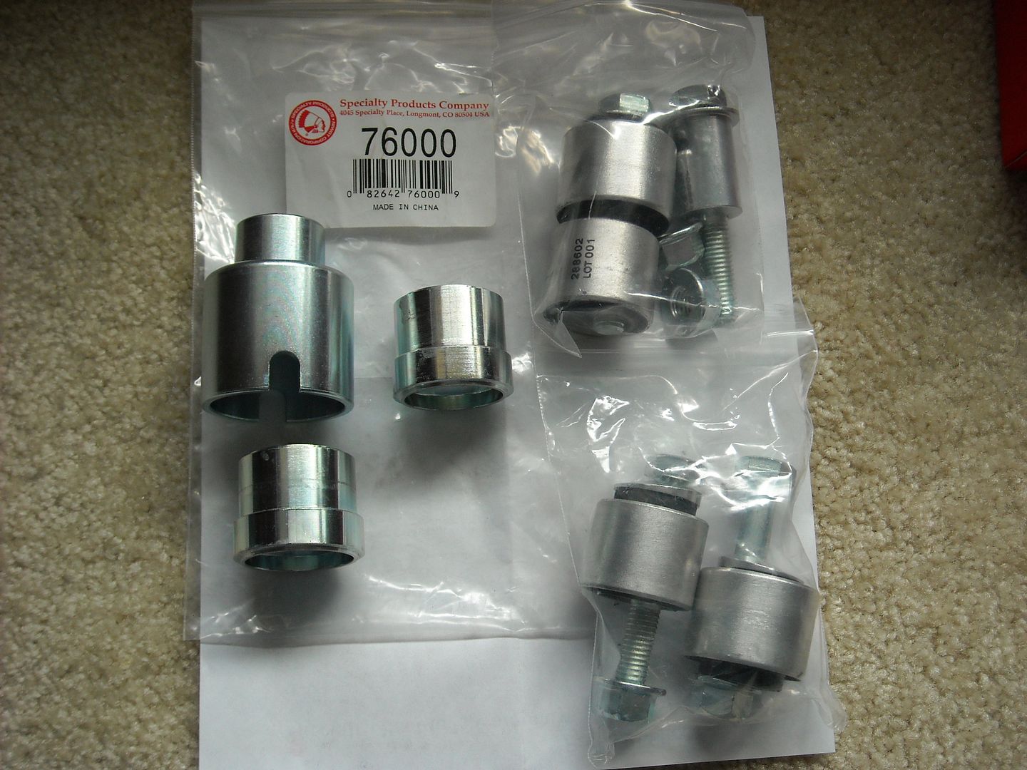
Above: Parts and pieces needed from SPC. SPC 76000, and two SPC 28860 bushing kits.
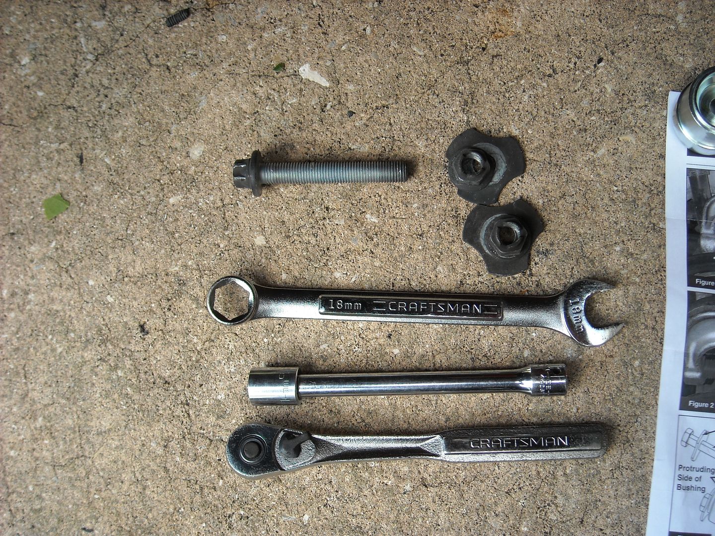
Below: Few tools needed for the process. 18mm 6-point wrench, 14mm 12- point socket, 6 inch extension, 3/8" ratchet, dial or digital caliper etc.
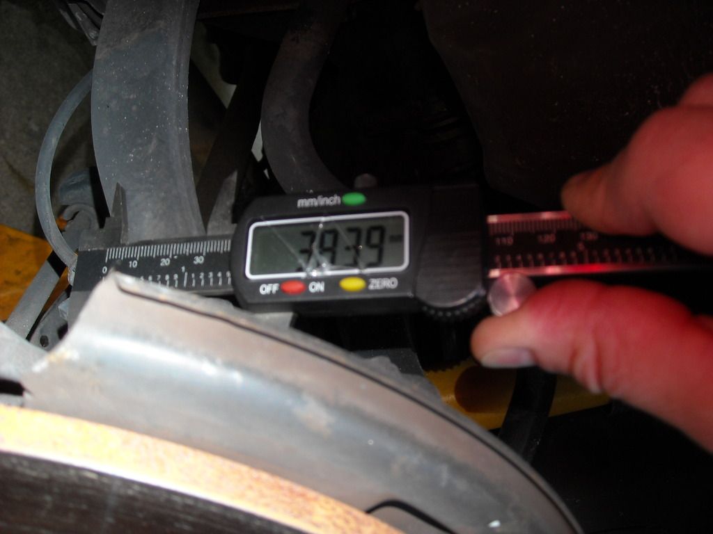
Above/Below: Begin with old bushing measurements. Should be 41.5mm for the one, and 38.5mm for the other. Instructions say to call SPC if your differ by more than .5mm. Mine were right on the money. Measuring can be difficult due to locaiton, but make sure they are at least in the ball park and move forward. Verification measurements will be made later as well.

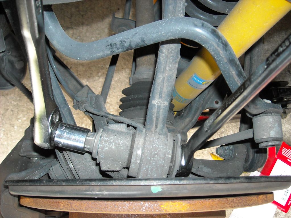
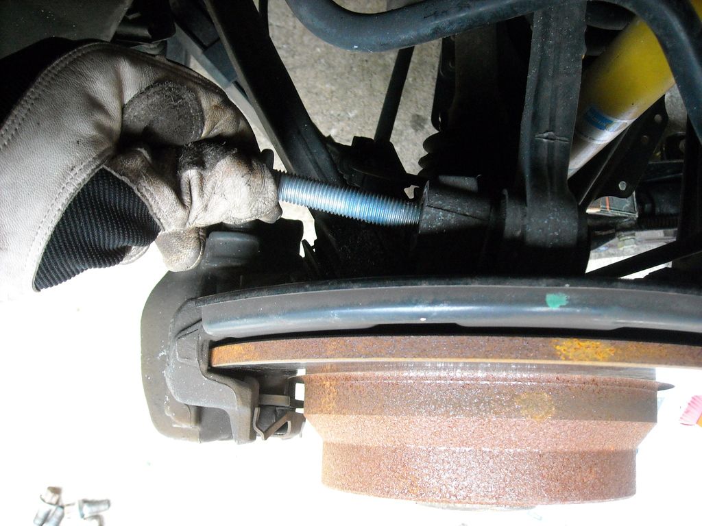
Above: Bolts start to come out.
Below: Here is the removed bolting and Tri-lobe washer the instructions talk about.

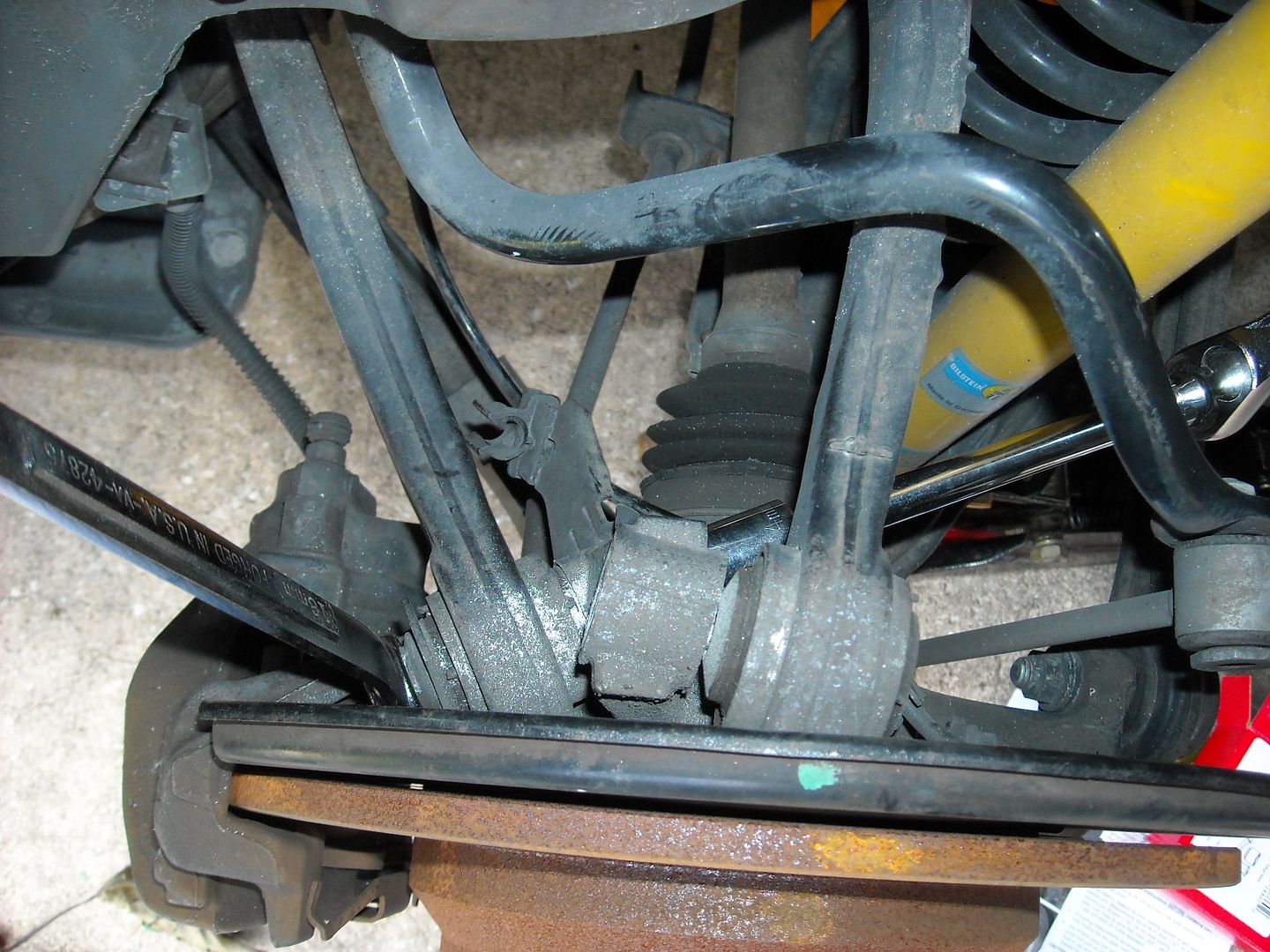
Above: Moving on to the other bolt now.
Below: Out they come!

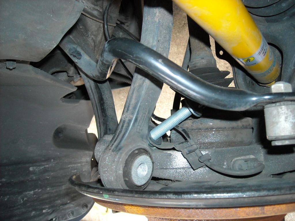
Above: Don't forget about the cable bracket. Make sure it goes back in during re installation.
Below: Now we can remeasure and verify the bushing diameters are correct. Close enough to keep on going in my mind.

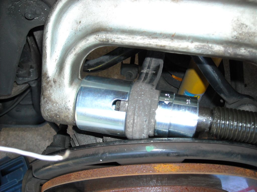
Above: SPC76000 kit with the correct 41.5mm adapters are put in the press tool and made ready.
Below: We have movement! All in all it didn't take huge amounts of torque to get it pressed out. Gets easier the farther out you push it.

Above: Out it comes.
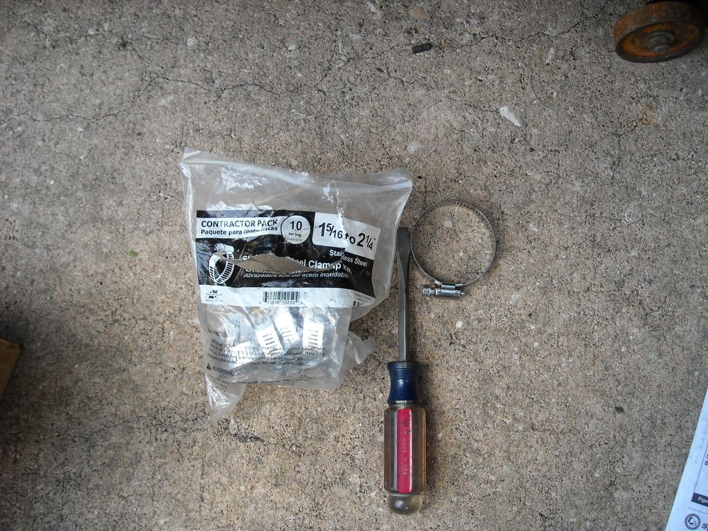
Below: Grab a heavy duty zip tie or two, some rope, or hose clamp like I did.
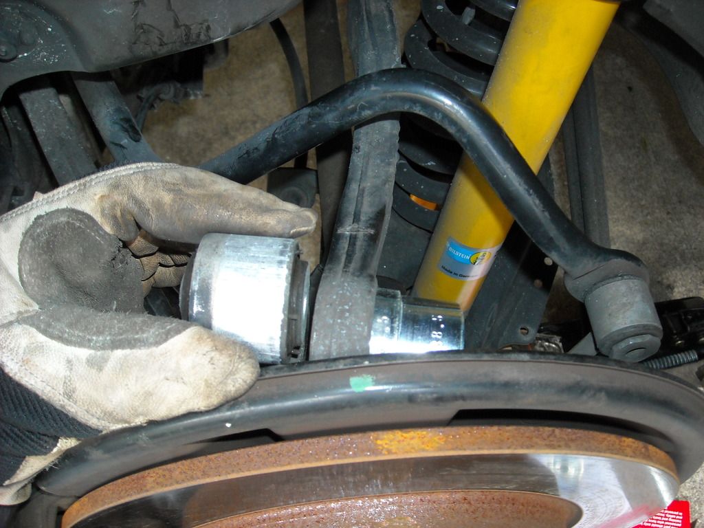
Above: Hose clamp to assist in keeping the lower arm in a position to allow the press to be used.
Below: Lift it up as far as possible and install the hose clamp.

New 4 in 1 Ball Joint Deluxe Service Kit Tool Set 2WD 4WD Free Shipping | eBay
Most likely your local Autoparts house has a free rental program and you could get it that way.
Here are some photos of the process on the rear drivers side of our W211:

Above: Parts and pieces needed from SPC. SPC 76000, and two SPC 28860 bushing kits.
Below: Few tools needed for the process. 18mm 6-point wrench, 14mm 12- point socket, 6 inch extension, 3/8" ratchet, dial or digital caliper etc.


Above/Below: Begin with old bushing measurements. Should be 41.5mm for the one, and 38.5mm for the other. Instructions say to call SPC if your differ by more than .5mm. Mine were right on the money. Measuring can be difficult due to locaiton, but make sure they are at least in the ball park and move forward. Verification measurements will be made later as well.


Above: Bolts start to come out.
Below: Here is the removed bolting and Tri-lobe washer the instructions talk about.


Above: Moving on to the other bolt now.
Below: Out they come!


Above: Don't forget about the cable bracket. Make sure it goes back in during re installation.
Below: Now we can remeasure and verify the bushing diameters are correct. Close enough to keep on going in my mind.


Above: SPC76000 kit with the correct 41.5mm adapters are put in the press tool and made ready.
Below: We have movement! All in all it didn't take huge amounts of torque to get it pressed out. Gets easier the farther out you push it.


Above: Out it comes.
Below: Grab a heavy duty zip tie or two, some rope, or hose clamp like I did.

Above: Hose clamp to assist in keeping the lower arm in a position to allow the press to be used.
Below: Lift it up as far as possible and install the hose clamp.


