Mercedes-Benz Forum banner

Warm up regulator (WUR) Calibration

102K views 22 replies 14 participants last post by  YianniTrakas  
#1 · (Edited)
Warm up regulator (WUR) Calibration / Control pressure calibration or adjustment

How to calibrate the k-jetronic warm up regulator

Applies to: Most K-jetronic mercedes engines, the type without electronic lambda controls.

Why do we have to trash malfunctioning WURs? Why do we have to pay $300 or more for a mint unit, or buy one on ebay for $99 without knowing if it's OK?

Now here is the information on how to test and calibrate any warm up regulator!

70% of this info comes to you thanks to this PDF:
http://www.denalidrafting.com/porsche/wurfix.pdf

It would be a good idea to first read this pdf and then continue; what i'm going to do is clear any doubts that the PDF may leave, and give a more thorough way of testing and calibrating the WUR.

You will need a control pressure/system pressure gauge for the k-jetronic system, with a gauge from 0 to 6bar.

The fuel mixture is determined by the position of the air flow sensor plate. The air suction creates a downward force on the sensor plate, which moves the central pin inside the fuel distributor; this force is countered by the force that applies over this pin due to the control pressure.

So if this control pressure increases, the counter acting force for the air flow sensor is greater, then the mixture is smaller.

So what is the normal control pressure? It should be around 3.0 to 4.0 bar (more on the exact numbers later).

So the Warm Up Regulator is the element which sets the control pressure, and, when the engine is cold, lowers it, so the mixture is richer.

The warm up regulator takes as input the fuel output line on top of the fuel distributor, which, by itself is system pressure (5.0-5.6bar), and lets some of this pressure drain to the fuel return line, so the pressure is reduced. Then this pressure is called the "control pressure" (3.0-4.0 bar).

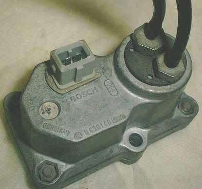
WUR -- Note: This one lacks the vacuum connector on top.
Image


Lets identify some parts in this image.
- At the left of the "BOSCH" label there is a pin, let's call it "THE PIN."
- Above the pin there is an electrical connector, "THE CONNECTOR." Notice it's being held in place by a C clip; you will remove it later.
- On top there are two fuel lines. The top one is the input (from fuel distributor), the bottom one is the drain/output (fuel return). Those two lines are part of a black circle thing, which is "THE DISC", which in the PDF is called as "the regulator".

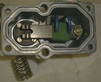
Now on this image from the top half of the WUR, from the inside:
Image


- At the left you see the bottom of "THE DISC".
- At the center of the disc there is "THE P SPOT", which presses the DIAPHRAGM inside THE DISC.
- The horizontal metal thing is the bimmetalic strip, "THE STRIP".
- The green thing is the electric heater for the strip, "THE HEATER", which is connected to "THE CONNECTOR"
- On the right side we see again the other side of "THE PIN"; screwed onto the pin is the nut and some washers below.

Not pictured here (sorry, i don't have more pictures right now)
- "THE SPRINGS", the base of the WUR body, the slim METAL POST that goes into the pin on the of bottom THE DISC, and the vacuum connections.

Now come on, dissasemble the WUR, it's very easy and it's unlikely that you will break anything if you don't force anything. A tip: To remove the STRIP, first remove the C clip that holds the CONNECTOR in place.

Theory of operation

The control pressure is directly regulated by the pressure exerted on THE P SPOT. Pressing THE P SPOT will increase the control pressure, no pressure on the P SPOT will drop the control pressure to 0.5 bar.

So, what the engine wants is a control pressure 3.0 to 4.0 bar when the engine is running, and, if the engine is cold, lower control pressure (say, 2.5bar), so the mixture is richer. Moreover, when accelerating, there are vacuum ports in the WUR that can affect the control pressure too, for more details on the vacuum side of the WUR please read:

http://www.benzworld.org/forums/w12...diagram-1982-500sec-500-sec-here.html?highlight=vacuum+diagram+for+500+sec+here

Now, look at your Warm Up Regulator. It has a bosch code, for example 0 438 140 068. The end number (068 in this case) is the number that gives us the intended calibration of the WUR. Now here are the calibration specs for each warm up regulator, straight from mercedes benz:

Specifications for some WUR used in the M116/117 and M110 engines.
Code:
WUR end code / control pressure at 20C(68F) / control pressure with engine at operating temperature (84C) / stabilization time / notes

061 / 1.6-2.0 bar / 3.4-3.8? / 3-6 min?
068 / 1.8-2.2 bar / 3.4-3.8? / 3-6 min?
030 / 1.2-1.6 bar / 3.4-3.8  / 3-6 min
031 / 1.2-1.6 bar / 3.0-3.4  / 3-6 min / "USA California version"
041 / 1.4-1.8 bar / 3.6-4.0  / 3-6 min / "USA Federal high altitudes"
056 / 1.2-1.6 bar / 3.4-3.8  / 2-4 min / In my car, which is a french euro 500 SEC.
 
#2 · (Edited)
(Continued)

So, as you can see, the usual control pressure should be 3.4 to 3.8 bar, but some WUR will give a bit lower or higher control pressures, if the mixture should be richer or leaner in special cases (for example, high altitudes).

Now, an interesting note: The 3mm allen screw on the top of the airflow sensor housing, also known as the "CO adjustment screw" will set the initial lambda (air to fuel ratio) on IDLE, but on the rest of RPMs, the lambda will be controlled by the control pressure. Thus, a badly calibrated control pressure cannot be satisfactorily compensated by fiddling with the CO adjustment screw.

The P SPOT is constantly pressed by the SPRINGS inside the warm up regulator. [More precisely, the P SPOT is pressed by the METAL POST, which is pressed by a plate on top of the springs.]

But there is a counterforce, provided by THE STRIP, which is temperature dependent and acts on top of the SPRINGS. The STRIP is heated by the engine block heat and by the HEATER.

When the car is WARM [84C], the STRIP gives no significant counterforce. When the car is COLD, the STRIP gives significant counterforce, which relieves the pressure on the P SPOT and thus lowers the control pressure.

Even if the car is cold, the HEATER will heat the STRIP thanks to the electric current (12V) that is continuosly on whenever the engine is running. So, when you turn the car in the morning, the HEATER will slowly increase the temperature of the strip, to slowly pseudo-cancel the enrichment. This cancellation should happen in the "stablization time" of the specs [2-6 minutes]. But my mercedes engine manual is not clear on what the control pressure should be after the strip is heated but the engine block has not reached 84C!

So, now the testing and calibration procedure:

STEP 1 - Testing the diaphragm inside the DISC

1. Dissasemble the WUR, leaving only the top half. Remove the springs and the metal post. You don't need to remove the strip. The goal is to let the P SPOT be free from any kind of force pressing it.

2. Connect the control pressure measuring gauge. One hose goes to the fuel line that is on top of the fuel distributor, the other goes to the input of the warm up regulator. For now, we are only going to use the top half of the warm up regulator.

3. [W126 1982 to 1984] Jumper jacks 7 and 8 of the fuel pump relay socket so the fuel pump stats running and doing that buzzing sound. For W126 Models before 1982 jumper jacks 1 and 2.

4. Turn the ignition on so the pump starts running (but the engine doesn't.) Visually check that no fuel is dripping from the connectors!

Now watch the pressure. It should be more or less 0.5bar.

5. Now apply pressure on the P SPOT until the pressure rises. If you were able to make it rise above 4-4.5 bar, CONGRATULATIONS! the steel diaphragm inside the DISC is ok!!

If the pressure doesn't rise more than 4-4.5 bar, something is wrong inside that DISC. Remove the 4 flat screws, inspect the diaphragm, clean it and/or replace it. Also replace the tiny o-ring below the diaphragm, if it's well worn.

Also, it is important to check the fuel filter mesh inside the input port of the WUR; make sure it's clean. This is a common problem.

STEP 2 - Testing the HEATER

1. Put the fuel pump relay back into place. This is important in this step!

2. Turn the engine on. It will run with a very rich mixture (because the control pressure is like 0.5 bar.)

2. Test the plug that goes into the CONNECTOR. Is 12V (or more) present on the plug? If not, you'll have to troubleshoot that. The voltage comes from pin 7 of the fuel pump relay [W126, 1982-1984], or pin 1 [W126, 1981].

3. Plug the plug into the CONNECTOR. Now touch the green thing, that is, the HEATER of the STRIP. It should slowly get warm to the touch. I doubt it will burn you, though. If it doesn't feel slightly warm after, say, 1 minute, then you'll have to replace the HEATER/STRIP combination.

Note - i am assuming that the thermocouple strip itself will never ever fail from bending according to temperature.

4. Turn off the engine.

STEP 3 - Testing Pseudo-WARM control pressure

1. Jumper the fuel pump relay so the fuel pump will run when ignition is on.

2. Remove the heater&STRIP from the top half of the WUR body.

3. Assemble the WUR back again with all its pieces except heater&strip, so you have a full WUR without the heater&STRIP.

TIP: Put grease between the P SPOT and the metal post, so the metal post sticks to the P SPOT. This will make assembly a whole lot easier. Assemble the WUR by putting the springs over the base, then the metal cap that goes over the springs, then put the metal post over the p-spot (with grease, remember?), place the top half of the WUR in upright position over the base until the metal post centers over the metal-cap-that-goes-over-the-springs; then tighten the screws at the bottom of the WUR.

4. Now turn the fuel pump on and measure control pressure. If it's 3.5 bar or over [mine was 4bar], we're ok. If is lower, then those springs are not exerting enough pressure, stretch them or replace with other similar springs from another WUR, a hardware store, etc.
 
#3 · (Edited)
Continued...

STEP 4 - Setting cold control pressure

Now here is the nice part here.

1. Disassemble the WUR. Yes, again.

2. Take a hammer and some screwdriver and bang THE PIN from the inside of the WUR, until it sticks some 1mm or 2mm out of the top of the warm up regulator. NOTE: I assume you have removed the STRIP and the nut&washers on the PIN.

This will make sure no STRIP counterforce will act on the springs and thus the control pressure will not be affected by the STRIP.

3. Put the STRIP back again into place, put the washers and nut in the order you found them. Make sure the strip is aligned with the P SPOT.

4. Make sure the strip and WUR body are at ambient temperature [20C/68F]

5. Assemble the WUR fully, with strip, springs and everything. Do not plug the CONNECTOR. Now turn the engine on. The control pressure should be the same you had on STEP 3, for example, 4 bar.

6. Now, looking at the WUR from the top, punch THE PIN with a hammer (& some screwdriver/pointed metal thing). Make it go down little by litlle (say, 1mm each punch), until the control pressure DROPS a little bit.

7. Once the control pressure has dropped a bit, continue punching the PIN but more carefully, with very soft, slight punches, dropping the control pressure 0,1 bar with each punch, until you get it down to the pressure specified as COLD control pressure [20C/68F] for your warm up regulator,
which will be 1.2-2.2 bar (look at my specifications table.)

STEP 5 - Setting warm control pressure

Now you have set the cold control pressure. Let's now check the WARM control pressure!

1. Turn off the engine, make sure the fully-assembled WUR is tightly fixed in place, so it will receive the engine block heat.

2. Plug the CONNECTOR back, and turn the engine on.

3. Look at the control pressure. It should start in the setting you set at STEP

4. Let the engine warm to 84C-90C, and give it plenty of time so the water temperature becomes also the block temperature and that becomes also the WUR temperature. The control pressure should RISE slowly, slowly...

It should rise to more than 3.0 bar. If it rises more than 3.8 bar, then something is wrong... Have you checked the fuel mesh filter on the input port of the WUR? Anyway, you can workaround this problem by punching the PIN back in a little more.

5. Now as the control pressure rises and the engine keeps running [after the water is 84C, give it 5 minutes at least!], there will be a moment in which the control pressure does not rise anymore. Is the pressure OK according to the specs for your warm up regulator (see table above)? If it's still low, how can you raise it?

Now here is the magic trick. The DISC can also be puched in, just like the PIN. So, with the engine running and using a big screwdriver and rubber hammer, punch the DISC so it goes more deeply into the WUR. We're talking fractions of milimeters here; it won't look as it is moving but the control pressure will rise slowly, like 0.1 bar.

Keep punching until you get the desired warm control pressure. I set mine in 3.4 bar.

STEP 6 - Mixture adjustment/emissions

With the car at operating temperature, get an exhaust gas analizer (or go to a shop that gives the exhaust gas analyzing service) and adjust the CO screw on the top of the airflow housing (3mm allen screw), until you get the CO/lambda to the specified levels for your car and by the law.

[Of course i'm assuming other things are ok, such as the vacuum circuit, the EGR valve, etc etc etc ETC.]

STEP 7 - Passion for perfection

With the car cold (say, in the morning), check if it runs without problems. If it doesn't, and other things are OK (such as the vacuum circuit), then you will probably benefit from lowering the cold control pressure, that is, go to STEP 4, then steps 5 and 6.

The end

Ok, i hope this information will be of benefit to forum members. Hopefully i will add later some information on the vacuum diaphragm that is inside the warm up regulator. And some diagrams.

Greetings,
Flavio.
 
#10 ·
Continued...

STEP 4 - Setting cold control pressure

Now here is the nice part here.

1. Disassemble the WUR. Yes, again.

2. Take a hammer and some screwdriver and bang THE PIN from the inside of the WUR, until it sticks some 1mm or 2mm out of the top of the warm up regulator. NOTE: I assume you have removed the STRIP and the nut&washers on the PIN.

This will make sure no STRIP counterforce will act on the springs and thus the control pressure will not be affected by the STRIP.

3. Put the STRIP back again into place, put the washers and nut in the order you found them. Make sure the strip is aligned with the P SPOT.

4. Make sure the strip and WUR body are at ambient temperature [20C/68F]

5. Assemble the WUR fully, with strip, springs and everything. Do not plug the CONNECTOR. Now turn the engine on. The control pressure should be the same you had on STEP 3, for example, 4 bar.

6. Now, looking at the WUR from the top, punch THE PIN with a hammer (& some screwdriver/pointed metal thing). Make it go down little by litlle (say, 1mm each punch), until the control pressure DROPS a little bit.

7. Once the control pressure has dropped a bit, continue punching the PIN but more carefully, with very soft, slight punches, dropping the control pressure 0,1 bar with each punch, until you get it down to the pressure specified as COLD control pressure [20C/68F] for your warm up regulator,
which will be 1.2-2.2 bar (look at my specifications table.)

STEP 5 - Setting warm control pressure

Now you have set the cold control pressure. Let's now check the WARM control pressure!

1. Turn off the engine, make sure the fully-assembled WUR is tightly fixed in place, so it will receive the engine block heat.

2. Plug the CONNECTOR back, and turn the engine on.

3. Look at the control pressure. It should start in the setting you set at STEP

4. Let the engine warm to 84C-90C, and give it plenty of time so the water temperature becomes also the block temperature and that becomes also the WUR temperature. The control pressure should RISE slowly, slowly...

It should rise to more than 3.0 bar. If it rises more than 3.8 bar, then something is wrong... Have you checked the fuel mesh filter on the input port of the WUR? Anyway, you can workaround this problem by punching the PIN back in a little more.

5. Now as the control pressure rises and the engine keeps running [after the water is 84C, give it 5 minutes at least!], there will be a moment in which the control pressure does not rise anymore. Is the pressure OK according to the specs for your warm up regulator (see table above)? If it's still low, how can you raise it?

Now here is the magic trick. The DISC can also be puched in, just like the PIN. So, with the engine running and using a big screwdriver and rubber hammer, punch the DISC so it goes more deeply into the WUR. We're talking fractions of milimeters here; it won't look as it is moving but the control pressure will rise slowly, like 0.1 bar.

Keep punching until you get the desired warm control pressure. I set mine in 3.4 bar.

STEP 6 - Mixture adjustment/emissions

With the car at operating temperature, get an exhaust gas analizer (or go to a shop that gives the exhaust gas analyzing service) and adjust the CO screw on the top of the airflow housing (3mm allen screw), until you get the CO/lambda to the specified levels for your car and by the law.

[Of course i'm assuming other things are ok, such as the vacuum circuit, the EGR valve, etc etc etc ETC.]

STEP 7 - Passion for perfection

With the car cold (say, in the morning), check if it runs without problems. If it doesn't, and other things are OK (such as the vacuum circuit), then you will probably benefit from lowering the cold control pressure, that is, go to STEP 4, then steps 5 and 6.

The end

Ok, i hope this information will be of benefit to forum members. Hopefully i will add later some information on the vacuum diaphragm that is inside the warm up regulator. And some diagrams.

Greetings,
Flavio.
 
#4 ·
Wow, great thread, thanks.

I have a '86 300 SL (euro spec) with an inline 6 cylinder (103.982) and am having a rough idle when in Drive at a stop light. My vacum lines seem to be ok from what I've checked and maybe it's the WUR the problem.

If you can post more pics that would be great too.

Cheers
 
#5 ·
The warm up regulator does not drain off the main system pressure line, instead it acts on the differential control pressure across the metering piston. Affecting that makes the system think more air is flowing so more fuel is injected. Instead of all this goings on consider the ideal setup like on early Euros. On these cars you simply make sure the warm up regulator totally shuts off by room temperature (or as it gets heated from the heating element). You can do this with air. When you are sure it's off you set the mixture at the tower and you're done.
 
#7 ·
Additional links

I have been looking into this problem and here are a couple more links that might be useful

Adding a Fuel pressure gauge to your CIS setup.

In-dash fuel pressure gauge for CIS - Pelican Parts Technical BBS

Fuel Pressure Gage - Pelican Parts Technical BBS

Modifying your WUR to enable easier fuel pressure adjustments.

Modified my WUR - Page 2 - Pelican Parts Technical BBS

WUR Strip down and rebuild

http://www.jtresto.com/e21/WURServicing.pdf

CIS Primer

CIS Primer for the Porsche 911


I know most of these links are to Porsche sites but they have the same injection system as Mercedes of the same vintage

New link for the 500SEC Vacuum Diagram as the old link just points to the DIY Thread and not the real posting.
http://www.benzworld.org/forums/w126-s-se-sec-sel-sd/1375331-vacuum-diagram-1982-500sec-500-sec.html
 

Attachments

  • Like
Reactions: CheckEngine
#16 · (Edited)
Hello. I know this is an old thread, but I think my input will still be relevant here.
I have a Warm-Up Regulator (WUR). I cleaned its channels with carburetor cleaner, but there’s still resistance when trying to blow through the intake channel.
I disassembled it, and if I remove the spring, the channel clears easily. This makes me think the issue lies in the WUR’s original calibration.
Could you please advise:
  1. What’s the easiest way to remove the plug covering the adjustment screw (photo1)? Will drilling it out compromise the vacuum seal?
  2. Theoretical question: When I apply vacuum (simulating the intake manifold), the piston pushes the small spring upward, which seems to close the channel. I always thought the channel should open instead to enrich the mixture. What’s the logic here?
 

Attachments

#17 ·
Curious if anyone knows the answer to this as well, I recently was asking this as I found someone else on another forum talking about adjusting the drift using a punch to adjust the vacuum enrichment. I only get a couple psi temporary bump when accelerate/apply vacuum to it.
 
#19 ·
I saw this and just wanted to share something I found to be helpful when I refreshed my WUR a while ago. Unfortunately, I can't recall exactly where I learned of this but it really makes the adjustment process a lot easier. I've attached a picture, and what you're looking for is the stainless steel Alan screw used as a stop/limiter. Oh, and before you get to installing it back in the car, really make sure the whole unit is completely sealed and holds the necessary vacuum.
Image
 
#23 ·
When you were setting your system and control pressures, did you tend to try and stay in the middle of the range one both? The reason I ask is because I can't quite find the sweet spot between cold vs hot tunning or idle vs cruise tunning. Hope that makes sense.
I saw this and just wanted to share something I found to be helpful when I refreshed my WUR a while ago. Unfortunately, I can't recall exactly where I learned of this but it really makes the adjustment process a lot easier. I've attached a picture, and what you're looking for is the stainless steel Alan screw used as a stop/limiter. Oh, and before you get to installing it back in the car, really make sure the whole unit is completely sealed and holds the necessary vacuum. View attachment 2948039
Appreciate it. I ended up doing the cold pin the manual way, and I tot the mod to the bottom pin. So now I'm going from 2.2 bar at 75F to 3.4 when fully war.