

As many know, the tachometer amplifier is a weak point of these cars. While stuffing something into the cap and re-tightening can work temporarily, I believe I have found a more permanent and cheap solution. After searching multiple auto parts yard for a tachometer amp, failing to find one, and still refusing to drop $90+ for a new one, I decided to go to work on my faulty unit. The short explanation for my repair is to re-solder the board and all connections. For more details, follow along as I show you how I fixed my 1981 300TDs tachometer amp with no new parts and in a more thorough way.
I apologize in advance that I don't have pictures for some of the in between tasks. Pictures were originally taken for my own reference prior to my idea of doing a write-up.
1) Remove the inner amplifier unit from the amps cylindrical housing. The inner housing shown below is connector pin side down. The silicone covered circuit is not there because I had already removed it; yours will not be an empty casing like in the picture.
![]()
2) Now separate the circuit from the inner plastic housing. The circuit board is covered by the white silicone glue. Around the perimeter of silicone side there are 3 clips that hold the board in the housing. There are also 3 clips around the silver pins which are centered around a central hole. As you gently pull back the clips on the silicone side, push the circuit out of the housing using something like the eraser side of a pencil and push the pencil through the large central hole on the pin side. A plastic disk should come out with the circuit holding the pins as shown below. Keep the wires in their respective positions for proper reconnection later. You should end up with the picture below.
![]()
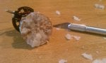
3) Its once you have it out... the tedious work begins. Don't get discouraged! It will all be worth it in the end! You need to *carefully* remove the silicone from the circuit board. I used my X-ACTO knife to scrape it off a little piece at a time. The blade tip was already snapped off from a previous job but it actually made the job easier. I'll let you know it took me almost a total of 3 hours to remove it all; 2 for the bulk and an hour for the tiny stuff. Following up with a wire brush may be a good idea. Be sure to take breaks.
(Although the board blocks the view of the blade tip, the blade pretty much stops where the circuit board blocks the view. Remember, these pictures were not originally taken with the intention of being used here)
![]()
4) BE SURE TO REMOVE AS MUCH AS POSSIBLE FROM THE JOINTS. Whatever is left will melt and burn when you solder if it's on the joints. That could contaminate the molten solder and cause a bad connection. Break out the soldering iron. Most/all of the joints you will likely want to add solder to when re-melting the solder. Be sure not to bridge any joints, thoroughly heat the joint when soldering, and add enough solder for a thorough connection; no rationing of solder here. Re-solder the "wire-to-pin" joints as well for good measure. Don't overlook the fact that the pins conduct heat and should not be held steady using your bare hands while soldering. Remember; keep the wires in their respective positions so they connect at the right points under the hood. This took me 2-3 hours too. Don't rush, this could be a one time job if you do it right but if you get lazy, you could end up wasting your own time and of course, take breaks; you don't have to do this in one day.
![]()
5) THE HARD WORK IS DONE! Time to test! Go ahead and use needle nose pliers to push each pin into its respective port. I didn't reassemble my amp at this point in case it didn't work or needed a point soldered.
![]()
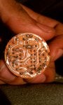
6) If step five ended in success, and I hope it did, go ahead and protect your hard work with a nice coating of hot glue or silicone where the old stuff was on the board.
![]()
7) Fully reassemble the tachometer amplifier if you so choose and enjoy the fruit of your labor!
PS: Sorry if I missed anything, this was kinda written in haste and is my first write-up. Nevertheless I hope it is helpful and you are as successful as I was.
I apologize in advance that I don't have pictures for some of the in between tasks. Pictures were originally taken for my own reference prior to my idea of doing a write-up.
1) Remove the inner amplifier unit from the amps cylindrical housing. The inner housing shown below is connector pin side down. The silicone covered circuit is not there because I had already removed it; yours will not be an empty casing like in the picture.

2) Now separate the circuit from the inner plastic housing. The circuit board is covered by the white silicone glue. Around the perimeter of silicone side there are 3 clips that hold the board in the housing. There are also 3 clips around the silver pins which are centered around a central hole. As you gently pull back the clips on the silicone side, push the circuit out of the housing using something like the eraser side of a pencil and push the pencil through the large central hole on the pin side. A plastic disk should come out with the circuit holding the pins as shown below. Keep the wires in their respective positions for proper reconnection later. You should end up with the picture below.

3) Its once you have it out... the tedious work begins. Don't get discouraged! It will all be worth it in the end! You need to *carefully* remove the silicone from the circuit board. I used my X-ACTO knife to scrape it off a little piece at a time. The blade tip was already snapped off from a previous job but it actually made the job easier. I'll let you know it took me almost a total of 3 hours to remove it all; 2 for the bulk and an hour for the tiny stuff. Following up with a wire brush may be a good idea. Be sure to take breaks.
(Although the board blocks the view of the blade tip, the blade pretty much stops where the circuit board blocks the view. Remember, these pictures were not originally taken with the intention of being used here)
4) BE SURE TO REMOVE AS MUCH AS POSSIBLE FROM THE JOINTS. Whatever is left will melt and burn when you solder if it's on the joints. That could contaminate the molten solder and cause a bad connection. Break out the soldering iron. Most/all of the joints you will likely want to add solder to when re-melting the solder. Be sure not to bridge any joints, thoroughly heat the joint when soldering, and add enough solder for a thorough connection; no rationing of solder here. Re-solder the "wire-to-pin" joints as well for good measure. Don't overlook the fact that the pins conduct heat and should not be held steady using your bare hands while soldering. Remember; keep the wires in their respective positions so they connect at the right points under the hood. This took me 2-3 hours too. Don't rush, this could be a one time job if you do it right but if you get lazy, you could end up wasting your own time and of course, take breaks; you don't have to do this in one day.
5) THE HARD WORK IS DONE! Time to test! Go ahead and use needle nose pliers to push each pin into its respective port. I didn't reassemble my amp at this point in case it didn't work or needed a point soldered.

6) If step five ended in success, and I hope it did, go ahead and protect your hard work with a nice coating of hot glue or silicone where the old stuff was on the board.

7) Fully reassemble the tachometer amplifier if you so choose and enjoy the fruit of your labor!
PS: Sorry if I missed anything, this was kinda written in haste and is my first write-up. Nevertheless I hope it is helpful and you are as successful as I was.


