Mercedes-Benz Forum banner

Warning indicator bulb replacement GenII

9.8K views 25 replies 12 participants last post by  therling  
#1 · (Edited)
September 2022. Updated to include information on replaced components. See post # 19 below.

It was annoying to me that the low coolant light was burned out, so I figured I'd replace it. Not that I need it, I check all the fluids regularly.

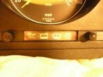
I took out the instrument cluster and found that on my 560SL, the four center warning lights are part of a "warning module," part number 1075420127. Evidently they expect you to replace the whole thing for $150, even if it's just got one 15 cent bulb burned out.


The back of the module is the brown circuit board below the speedo. Remove the two small screws and the module pulls right out.
Behind the plastic strip that has the icons, the bulbs are found down at the end of a series of shafts, and are soldered to a circuit board.


I found that you can take the module apart by pulling the rear most circuit board.


Then after removing a small screw, and lifting up and out, the board with the bulbs comes out.

Using a soldering iron and a soldering sucker, I removed the bulb from the PCB. Those bulbs are different from the other cluster bulbs, they are frosted and say "14 Volts" on the side. I decided to just replace the bulb with a regular cluster bulb, so I bent the terminals on a bulb so they stuck out and I soldered it into place. I could have used an LED, but I didn't feel like sorting out the polarity of the contacts.
More on the next post.
 

Attachments

#2 ·
I always like to clean any electrical contacts while I'm in there. My tool of choice is a fiberglass pen. It does a great job of getting contacts shiny but you have to mind the tiny bits of glass fiber that come off it.

Reassembling the module is a simple matter of fitting the bulb board back in, and sliding the main board in, being careful to get it into the slots on the inside of the body of the module. Those four blade-like contacts have a matching socket on the top of the PCB.


Then, put the plastic "lens" back on the front. It's keyed with a small pin so you can't get it in backwards. The module also can only be inserted into the instrument cluster one way.

So now I've got all my instrument cluster bulbs functioning as they should be.
 
#4 ·
God write up with detailed pictures......deserves to be in the EGv107!

I am the same way, the smallest things just bugs the hell out of me ( some, including my wife call it OCD).
 
#11 ·
Nice job and write up.

Now...what the fuck is a fiberglass pen and what is it traditionally used for?

Oh ya...google....standby...
 
#12 ·
TOP QUALITY FIBRE PEN

Lots of Uses

Ideal for cleaning printed circuit boards before and after soldering

Ideal for cleaning corroded electronic boards and components

Ideal for cleaning terminals and connectors

Ideal for cleaning corrosion in mobile phones and remote controls etc

Ideal for model trains etc


Once you have used one you will wonder how you managed without!
 
#18 ·
What? You are commenting on an almost 10 year old thread.

Feel free to update this thread with better photos and info.

And while you are at it...

If you haven't done it already....please complete your profile with year and model.

Trust me....this will help you in the long run.


---->click on your icon (top right hand corner of your screen)
----> click on Account Settings
---->go to Account Details
----> add vehicle details
---->ADD your make model YEAR
----> click save.
 
#19 ·
I can't recall why I failed to include information about the two resistors I had apparently replaced when I did this job. That blue arrow was on the photo when I dug it up out of the mists of time so I must have intended to write that up and post it.Those photos were done with an older digital camera with the wrong white balance. I've tried to correct for that by adjusting the colors.

The larger one is Orange Black Gold Gold, which tells me it's a 3 𝛀 1% tolerance 1 Watt metal foil type. The smaller resistor is Green Blue Red Red Brown, so that's 56.2K 𝛀, 1% tolerance 1/2 Watt, also metal foil. I'm sure a plain old 56K 1/2 Watt would do just as well.

It looks like I replaced some other resistors, probably they either were out of tolerance or just looked funny. It's a real pain in the ass to replace instrument cluster components because you have to remove the steering wheel.

Also, warning about the cluster printed circuit boards, they get brittle with age. I had the left hand one go bad on me and the fuel gauge stopped working. There must have been a hairline crack in the PCB. The meters are soldered directly onto the PCB, so it's difficult to trace what's on the board.

If I did that job today I'd likely replace that electrolytic capacitor in principle because those tend to go bad over time and test that transistor too.

One reason I like this car is that it uses good old fashioned through-hole replaceable components. Today it would be a million tiny SMTs that can't be replaced.
Image


Image
 
#23 ·
Resistors don't usually go bad, but if you put enough wattage into them the magic smoke inside them that makes them work digs a hole through the package and escapes.

Looking at the photo in Tomasz's post, # 17, you'll see what looks like some burned resistors. I can't find some of the original photos, but it looks like the 1 Watt resistor got fried as did the smaller one next to it. It's possible whatever surge took out the resistors also took out the bulb. Some of the others look kind of brown, like they were burned and I probably replaced them because they were out of tolerance or just didn't trust them to last, and I didn't want to have to pull the cluster again to replace them. As the manual often says "Replace in Principle."

Image
 
#22 ·
Speaking of while I was in there. While I was tracking those photos down, I found additional photos on parts of the instrument cluster I replaced not long after.

In May of that same year, there was a short in the dashboard and it burned off a trace on the PCB and all the lights went out. Unfortunately the only photos I can find are out of focus. I'm sure I soldered a hunk of wire to replace the missing trace.

Image


Then the next month, the odometer stopped working, so I had to pull the cluster for the third time and replace the gears which had dissolved and lost some teeth.

Image


Image


Lesson learned: while you have the instrument cluster out, reinforce that hunk of trace on the PCB and check the gears on the odometer. If they are brown with age, chances are they're ready to fail. Try to avoid having to pull the cluster three times in five months.
 
#25 ·
Ye-es, but I could be pedantic and say that if you raise the current then the wattage goes up unless there's an inversely proportional reduction of voltage. But I digress.

My guess would be that the design team which developed this set of warning lights may not have accurately estimated the amount of heat that this module would be exposed to, especially not for the 25 years mine was subject to. The guys who did the odometer gears didn't get those to last any longer either.

I am still mystified about the people behind the 1986-87 turd on the lid 3rd brake light. I could understand if it was one hastily to meet new US DOT regulations but that should have been fixed for the 87 model, not left until the 88 model came out.