NOTE....This thread contains some information and images borrowed from various published sources.
One part on the Mercedes autos that really get less than a second thought is the flex disc. In short the flex disc is the cousin to the universal joint or as it's more commonly called, the U-joint. It is the attachment point between the transmission and the drive shaft and the rear differential and the drive shaft. They are usually very robust, but like everything else they do and WILL fail, often at the most inconvenient time.
They are not hard to replace but since they are under the car, most people rarely check them. I always recommend checking them along with other items like CV boots, brake lines etc., at every oil change. If you see ANY cracking or wear areas on either the rubber or the metal potion, then I highly suggest replacing it. What happens if one fails while driving?
Glad you asked. Depending on your current speed, whether you are accelerating or not and whether the front or back flex disc fails will determine the damage.
This is what a nice new flex disc looks like. The whole piece is basically a big rubber disc with 6 metal holes. They usually are very strong, but can and do fail. Check for cracking in between where the bolts go with a very strong light. Any cracking at all and it needs to be replaced.
![Image]()
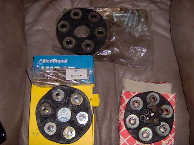
This is a good versus BAD flex disc.
![Image]()
A FAILING flex disc.
![Image]()
![Image]()
Damage from a failed flex disc can be catastrophic.
![Image]()
![Image]()
Good versus BAD propeller shaft.
![Image]()
Parts Required
There are many different part numbers (too many to list) over the years concerning the Flex Discs and attaching hardware. Please state your year and model when ordering.
Replacing the lock nuts is a must as they are one time use only.
Other parts to consider:
Center Hanger 123 410 10 81... item 32
Hanger Bearing 008 981 43 25... item 35
Rubber Boot 202 411 04 97... item 47
Centering Sleeve 115 410 00 32... items 14 / 29
![Image]()
Maintenance Manuals
Various sources of replacement instructions.
MB 107 manual (CD or hardcopy)
Job 41-050.......Prop Shaft Remove and Install
Job 41-100.......Hanger Bearing Replacement
Job 41-200.......Centering Sleeve Replacement
CHILTON Manual #48300
Job 7-20
HAYNES Manual # 63025
Chapter 7
TOOLS REQUIRED
Basic hand tools, a large adjustable wrench or 46MM (1 3/4 in) wrench and a Vise Grip chain pliers.
A bench vise is handy for replacing the centering sleeves and/or the hanger bearing.
The car will need to be elevated....so the required floor jack and jack stands or a lift or a pit.
NOTE: Tools required are listed in the various manuals.
![Image]()
![Image]()
Personal Experience
SIMPLE DISC REPLACEMENT
LINKS USED
Failure of the Flex Disc on a 126 Body Mercedes
Correct Flex PLate Placement of Bolts in Hole by 17thabn
Flex Disk Cracks, Your Opinions by roncallo
I Finally Started by nobby (post #26)
I Finally Started by nobby (post #34)
Failure of the Flex Disc on a 126 Body Mercedes
Correct Flex PLate Placement of Bolts in Hole by 17thabn
Flex Disk Cracks, Your Opinions by roncallo
I Finally Started by nobby (post #26)
I Finally Started by nobby (post #34)
One part on the Mercedes autos that really get less than a second thought is the flex disc. In short the flex disc is the cousin to the universal joint or as it's more commonly called, the U-joint. It is the attachment point between the transmission and the drive shaft and the rear differential and the drive shaft. They are usually very robust, but like everything else they do and WILL fail, often at the most inconvenient time.
They are not hard to replace but since they are under the car, most people rarely check them. I always recommend checking them along with other items like CV boots, brake lines etc., at every oil change. If you see ANY cracking or wear areas on either the rubber or the metal potion, then I highly suggest replacing it. What happens if one fails while driving?
Glad you asked. Depending on your current speed, whether you are accelerating or not and whether the front or back flex disc fails will determine the damage.
This is what a nice new flex disc looks like. The whole piece is basically a big rubber disc with 6 metal holes. They usually are very strong, but can and do fail. Check for cracking in between where the bolts go with a very strong light. Any cracking at all and it needs to be replaced.

This is a good versus BAD flex disc.

A FAILING flex disc.


Damage from a failed flex disc can be catastrophic.


Good versus BAD propeller shaft.

Parts Required
There are many different part numbers (too many to list) over the years concerning the Flex Discs and attaching hardware. Please state your year and model when ordering.
Replacing the lock nuts is a must as they are one time use only.
Other parts to consider:
Center Hanger 123 410 10 81... item 32
Hanger Bearing 008 981 43 25... item 35
Rubber Boot 202 411 04 97... item 47
Centering Sleeve 115 410 00 32... items 14 / 29

Maintenance Manuals
Various sources of replacement instructions.
MB 107 manual (CD or hardcopy)
Job 41-050.......Prop Shaft Remove and Install
Job 41-100.......Hanger Bearing Replacement
Job 41-200.......Centering Sleeve Replacement
CHILTON Manual #48300
Job 7-20
HAYNES Manual # 63025
Chapter 7
TOOLS REQUIRED
Basic hand tools, a large adjustable wrench or 46MM (1 3/4 in) wrench and a Vise Grip chain pliers.
A bench vise is handy for replacing the centering sleeves and/or the hanger bearing.
The car will need to be elevated....so the required floor jack and jack stands or a lift or a pit.
NOTE: Tools required are listed in the various manuals.


Personal Experience
SIMPLE DISC REPLACEMENT
- For a simple disc replacement, the 6 bolts need to be removed from the end that needs replacing. Three bolts on each flange...all six go through the disc. Discard the nuts.
- The prop shaft is in two pieces that can telescope or be removed in two complete halves.
- For a disc replacement, telescoping is enough.
- There is a 46MM nut near the center of the prop shaft that needs to be loosened.
- I used a small engraver to mark the location of all parts prior to loosening. The shaft is balanced and needs to go back together the way it came apart.
- I used the vise grip chain clamp to hold the shaft as I loosened the nut.
- Once loose, the shaft can be separated from the disc / corresponding flange on either the tranny or the diff end. It needs to be pulled straight out so that the centering sleeve doesn't get damaged. They are made of plastic and are $70 each!
- The new flex disc will have a line or arrow indicator.
- This needs to be lined up with either of the three bolt holes on the prop shaft flange.
- On a 5 speed, the disc will have German writing on one side. This side towards the prop shaft flange. In fact, that's what it probably says in German.
- Bolt the disc back on using, at a minimum, new nuts. I used all new hardware.
- These bolts need to be torqued as per the maintenance manual.
- Tighten up the telescoping nut in the center making sure all your engraved marks line up.