.
Bosch K-Jetronic Continuous Injection System Mechanical Fuel Injection Overview
15.1.1
Introduction and operational overview
15.1.2
The fuel tank
15.1.3
The fuel pump
15.1.4
The fuel pump relay
15.1.5
The accumulator
15.1.6
The fuel filter
15.1.7
Systems pressure
15.1.8
The airflow sensor
15.1.9
The fuel distribution unit
15.1.10
The warm up regulator
15.1.11
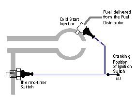
The cold start injector
15.1.12
The auxiliary air valve
15.1.13
The fuel injectors
15.1.14
System overview diagram
NOTE:- whilst working on any fuel system, care and attention should be taken to avoid the petrol coming in contact with any source of ignition, this can include: hot engine components, High Tension (HT) sparks and smoking. For further advice on good working practices, see our section on Health & Safety.
15.1.1 Introduction and operational overview of Bosch K Jetronic
This form of mechanical fuel injection has been used on the internal combustion engine for many years. Mechanical fuel injection systems first saw light of day at the turn of the century, however the following 100 years has seen the system evolve from a very basic and almost crude fuel delivery system, to the recent mass produced versions of the Bosch K and KE Jetronic. The mechanical fuel injection system has recently been overshadowed by modern electronic injection, which enables the use of lambda closed loop control. The electronically modified Bosch KE also has this capability although it never achieved the popularity of the pure mechanical system.
The system may seem very complicated at first, but it can be broken down into specific areas and fault finding is therefore made easier.
Fuel is delivered from the fuel pump to a metering (or fuel distribution) head and depending on the engine's temperature, the correct amount of fuel is delivered via the injectors to the engine. The injectors on this system spray fuel continuously in a fine atomised spray into the inlet manifold.
Cold start and the warm-up period are also catered for by a cold start injector and a reduction in the control pressure. The idle speed is increased by the auxiliary air valve.
The fuel pump will have the ability to provide a huge amount of fuel from the tank of which 99% will be returned. Due to the nature of this system, specialised equipment may be needed.
15.1.2 The Fuel Tank
The fuel tank is the obvious place to start in any fuel system explanation - unlike the tanks on early carburetor fuelled engines it is a sealed unit. This allows the natural gassing of the fuel to aid delivery to the pump by slightly pressurising the tank It may be noted that when the filler cap is removed, pressure is heard to escape. Filler caps are no longer vented as previously found.
15.1.3 The Fuel Pump
This type of high pressure fuel pump is denoted as a roller cell pump, with the fuel entering the pump and being compressed by rotating cells that force it through the pump at high pressure. The pump is capable of producing a pressure of 8 bar (120 psi) with a delivery rate of approximately 4 to 5 litres per minute.
Within the pump is a pressure relief valve that lifts off its seat at 8 bar to arrest the pressure should the filter, fuel lines or other eventualities cause it to become obstructed. The other end of the pump (output) is home to a non-return valve that, when the voltage to the pump is removed, closes the return and maintains pressure within the system, as illustrated in figure 6.1.
The normal operating pressure within this system is approximately 5 bar (75 psi) and at this pressure the current draw on the pump is 5 to 8 amps. Fuel passing across the fuel pump's armature will be subjected to sparks and arcing, this on the surface appears quite dangerous, but the absence of oxygen means that there will not be an explosion!
Some systems operate a small lift pump situated inside the tank. The supply voltage to the pump in the majority of cases is 12 volts.
Some systems do however operate at 6 volts, and see a higher voltage under cranking to pressurise the system faster. This voltage reduction is made possible by using a ballast resistor, which is then by-passed when cranking.
The voltage supply to the pump is via the fuel pump relay.
Roller cell fuel pump
Fig. 15.1.1
![Image]()
Figure 15.1.1 shows a cross section of an electric fuel pump.
15.1.4 The Fuel Pump Relay
This type of relay is known as a tachometric relay, which means that it only responds and sends a voltage to the pump when the engine is cranking or running. The relay receives a signal from the negative terminal of the coil - this confirms that the engine is turning.
This type of relay is used as a safety device: if the vehicle is involved in an accident when there is a possibility of a fuel line being fractured, the engine will stop due to a lack of fuel, the signal from the coil stops and the supply voltage to the pump is removed.
Typical fuel pump relay connections are as follows:
NOTE :- while the connections are correct for certain vehicles, the appropriate pins must be identified before testing. Certain relays also perform a pressurisation purge by allowing the pump to run for a second before shutting off, to prime the system.
The location of the relay will vary between motor manufacturers and is in no set position.
When fault finding or fuel pressure testing it will be necessary to have the pump running when the engine is stationary, this can be achieved by bridging terminals 30 and 87 with a small length of wire. For safety reasons it is good practice to insert a ten amp fuse into the bridging wire.
If the engine runs for a while but then stops, failing to restart for a few minutes, feel the relay to see if it is getting warm as this could be the faulty area. Bridging with the fused link wire will confirm the problem.
CAUTION :- do not be tempted to by-pass the relay by bridging between terminal 15 (switched live) and 87 (fuel pump) as this will start the car, but is potentially dangerous.
15.1.5 The Accumulator
The accumulator is the first of the components in the fuel system after the pump. This unit has an important role to fill in the operation of the Bosch K Jetronic system.
Its first job is to help smooth out any pulses in the flow of the fuel, this is achieved by passing the fuel through a series of baffles and into a chamber giving it slight capacitance and a much smother flow. Its other and possibly more important role is to maintain pressure within the system when the fuel pump has been switched off; this is achieved by the accumulator spring and diaphragm pushing against the fuel.
For the duration that the engine is running, the diaphragm will be against its stop within the spring's chamber. When the engine is stopped and all of the non-return valves close, the spring pressure against the diaphragm will maintain the residual or holding pressure and overcome any slight seepage.
Within the data books for this system, it is shown that the critical time for maintaining these pressures, is between 5 and 20 minutes. After a journey, when the engine is switched off, the under bonnet temperature increases causing the fuel in the lines to heat and it attempts to evaporate.
Maintaining the pressure eliminates this problem and ensures a clean start when the vehicle has been standing with a hot engine.
Accumulator
Fig. 15.1.2
![Image]()
Figure 15.1.2 shows an accumulator full of fuel.
15.1.6 The Fuel Filter
Due to the extremely fine tolerances within the Bosch K Jetronic system, it is vital that the filter has excellent filtration properties without impeding the flow on the fuel. The filter is a large metal canister with different fittings at either end to avoid the unit being installed incorrectly and compromising its efficiency. A visual inspection of the filter is not possible but the current draw of the fuel pump, measured in amps, can indicate a blocked or obscured filter.
The current can be recorded by inserting a multimeter in series with the circuit, the usual place to do this is to bridge the relay's terminal block. If however the relay is not easily accessible the fuse to the pump can be removed as this also provide a convenient place to measure the current.
A typical current draw will generally be between 5 to 8 amps. The current recorded will be lower if the systems pressure is less than the quoted specifications and higher if the flow of fuel is restricted in any way, for example: a blocked filter or a damaged fuel line.
Fuel filter
Fig. 15.1.3
![Image]()
Figure 15.1.3 shows an example fuel filter.
.
Bosch K-Jetronic Continuous Injection System Mechanical Fuel Injection Overview
15.1.1
Introduction and operational overview
15.1.2
The fuel tank
15.1.3
The fuel pump
15.1.4
The fuel pump relay
15.1.5
The accumulator
15.1.6
The fuel filter
15.1.7
Systems pressure
15.1.8
The airflow sensor
15.1.9
The fuel distribution unit
15.1.10
The warm up regulator
15.1.11
The cold start injector
15.1.12
The auxiliary air valve
15.1.13
The fuel injectors
15.1.14
System overview diagram
NOTE:- whilst working on any fuel system, care and attention should be taken to avoid the petrol coming in contact with any source of ignition, this can include: hot engine components, High Tension (HT) sparks and smoking. For further advice on good working practices, see our section on Health & Safety.
15.1.1 Introduction and operational overview of Bosch K Jetronic
This form of mechanical fuel injection has been used on the internal combustion engine for many years. Mechanical fuel injection systems first saw light of day at the turn of the century, however the following 100 years has seen the system evolve from a very basic and almost crude fuel delivery system, to the recent mass produced versions of the Bosch K and KE Jetronic. The mechanical fuel injection system has recently been overshadowed by modern electronic injection, which enables the use of lambda closed loop control. The electronically modified Bosch KE also has this capability although it never achieved the popularity of the pure mechanical system.
The system may seem very complicated at first, but it can be broken down into specific areas and fault finding is therefore made easier.
Fuel is delivered from the fuel pump to a metering (or fuel distribution) head and depending on the engine's temperature, the correct amount of fuel is delivered via the injectors to the engine. The injectors on this system spray fuel continuously in a fine atomised spray into the inlet manifold.
Cold start and the warm-up period are also catered for by a cold start injector and a reduction in the control pressure. The idle speed is increased by the auxiliary air valve.
The fuel pump will have the ability to provide a huge amount of fuel from the tank of which 99% will be returned. Due to the nature of this system, specialised equipment may be needed.
15.1.2 The Fuel Tank
The fuel tank is the obvious place to start in any fuel system explanation - unlike the tanks on early carburetor fuelled engines it is a sealed unit. This allows the natural gassing of the fuel to aid delivery to the pump by slightly pressurising the tank It may be noted that when the filler cap is removed, pressure is heard to escape. Filler caps are no longer vented as previously found.
15.1.3 The Fuel Pump
This type of high pressure fuel pump is denoted as a roller cell pump, with the fuel entering the pump and being compressed by rotating cells that force it through the pump at high pressure. The pump is capable of producing a pressure of 8 bar (120 psi) with a delivery rate of approximately 4 to 5 litres per minute.
Within the pump is a pressure relief valve that lifts off its seat at 8 bar to arrest the pressure should the filter, fuel lines or other eventualities cause it to become obstructed. The other end of the pump (output) is home to a non-return valve that, when the voltage to the pump is removed, closes the return and maintains pressure within the system, as illustrated in figure 6.1.
The normal operating pressure within this system is approximately 5 bar (75 psi) and at this pressure the current draw on the pump is 5 to 8 amps. Fuel passing across the fuel pump's armature will be subjected to sparks and arcing, this on the surface appears quite dangerous, but the absence of oxygen means that there will not be an explosion!
Some systems operate a small lift pump situated inside the tank. The supply voltage to the pump in the majority of cases is 12 volts.
Some systems do however operate at 6 volts, and see a higher voltage under cranking to pressurise the system faster. This voltage reduction is made possible by using a ballast resistor, which is then by-passed when cranking.
The voltage supply to the pump is via the fuel pump relay.
Roller cell fuel pump
Fig. 15.1.1

Figure 15.1.1 shows a cross section of an electric fuel pump.
15.1.4 The Fuel Pump Relay
This type of relay is known as a tachometric relay, which means that it only responds and sends a voltage to the pump when the engine is cranking or running. The relay receives a signal from the negative terminal of the coil - this confirms that the engine is turning.
This type of relay is used as a safety device: if the vehicle is involved in an accident when there is a possibility of a fuel line being fractured, the engine will stop due to a lack of fuel, the signal from the coil stops and the supply voltage to the pump is removed.
Typical fuel pump relay connections are as follows:
Terminal Number/Connection
30/Permanent battery live
31/Earth
1 or 31b/Coil negative
15/Switched 'Ignition on ' voltage
87/Output to fuel pump
30/Permanent battery live
31/Earth
1 or 31b/Coil negative
15/Switched 'Ignition on ' voltage
87/Output to fuel pump
NOTE :- while the connections are correct for certain vehicles, the appropriate pins must be identified before testing. Certain relays also perform a pressurisation purge by allowing the pump to run for a second before shutting off, to prime the system.
The location of the relay will vary between motor manufacturers and is in no set position.
When fault finding or fuel pressure testing it will be necessary to have the pump running when the engine is stationary, this can be achieved by bridging terminals 30 and 87 with a small length of wire. For safety reasons it is good practice to insert a ten amp fuse into the bridging wire.
If the engine runs for a while but then stops, failing to restart for a few minutes, feel the relay to see if it is getting warm as this could be the faulty area. Bridging with the fused link wire will confirm the problem.
CAUTION :- do not be tempted to by-pass the relay by bridging between terminal 15 (switched live) and 87 (fuel pump) as this will start the car, but is potentially dangerous.
15.1.5 The Accumulator
The accumulator is the first of the components in the fuel system after the pump. This unit has an important role to fill in the operation of the Bosch K Jetronic system.
Its first job is to help smooth out any pulses in the flow of the fuel, this is achieved by passing the fuel through a series of baffles and into a chamber giving it slight capacitance and a much smother flow. Its other and possibly more important role is to maintain pressure within the system when the fuel pump has been switched off; this is achieved by the accumulator spring and diaphragm pushing against the fuel.
For the duration that the engine is running, the diaphragm will be against its stop within the spring's chamber. When the engine is stopped and all of the non-return valves close, the spring pressure against the diaphragm will maintain the residual or holding pressure and overcome any slight seepage.
Within the data books for this system, it is shown that the critical time for maintaining these pressures, is between 5 and 20 minutes. After a journey, when the engine is switched off, the under bonnet temperature increases causing the fuel in the lines to heat and it attempts to evaporate.
Maintaining the pressure eliminates this problem and ensures a clean start when the vehicle has been standing with a hot engine.
Accumulator
Fig. 15.1.2
Figure 15.1.2 shows an accumulator full of fuel.
15.1.6 The Fuel Filter
Due to the extremely fine tolerances within the Bosch K Jetronic system, it is vital that the filter has excellent filtration properties without impeding the flow on the fuel. The filter is a large metal canister with different fittings at either end to avoid the unit being installed incorrectly and compromising its efficiency. A visual inspection of the filter is not possible but the current draw of the fuel pump, measured in amps, can indicate a blocked or obscured filter.
The current can be recorded by inserting a multimeter in series with the circuit, the usual place to do this is to bridge the relay's terminal block. If however the relay is not easily accessible the fuse to the pump can be removed as this also provide a convenient place to measure the current.
A typical current draw will generally be between 5 to 8 amps. The current recorded will be lower if the systems pressure is less than the quoted specifications and higher if the flow of fuel is restricted in any way, for example: a blocked filter or a damaged fuel line.
Fuel filter
Fig. 15.1.3

Figure 15.1.3 shows an example fuel filter.
.
cont.